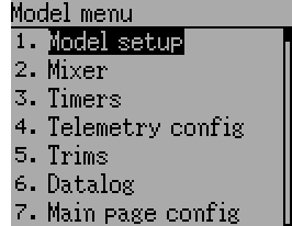
9. Model menu
The model menu allows selection, editing model configuration, alarms, logging and screen configurations. You can access the menu by pressing the ENT key to select the ‘Main menu’ and then again on ‘Model menu’.
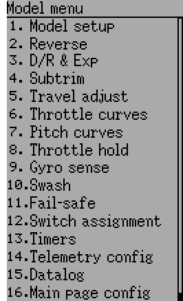
Depending on the selection you have done for the Mixer GUI in section Model setup (Std & Adv GUI), the model menu operation will be completely different.
The Advanced ‘2. Mixer’ page (Mixer (Adv GUI)) provides all of the functionality (and more) of the Standard Model.
| Advanced Model Menu | Standard Model Menu | ||
|
|
Note: The Advanced Mixer GUI is the default setting for all new models.
9.1. Model setup (Std & Adv GUI)
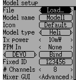
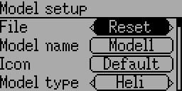
The model page provides various model configuration options.
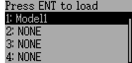
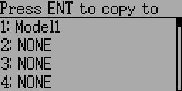
File: The File spin-box allows loading a new model, copying the existing model to a new location, resetting the current model to the default (all configuration is lost), and loading templates (see Predefined Model Templates). Note that changing models may result in a safety message being displayed (see Safety System).
|
|
Mixer GUI: Defines which graphical user interface (GUI) to use for this model. The ‘Advanced’ GUI is the default for Deviation. The ‘Standard’ GUI is only available for Helicopter models and more closely resembles the stock GUI.
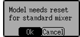
Standard mixer gui is designed for collective pitch helicopters with a flybar. It includes features spefic to those that aren’t needed on other aircraft, and may be missing features needed to properly control other aircraft. A flybarless collective pitch helicopter might benefit from some of the features of the standard GUI, it doesn’t need them and may need those missing features. You are strongly encouraged to use advanced mixer for all aircraft but collective pitch helicopters.
Note: If you switch from advanced mixer to standard mixer all data may be lost. Your data will be preserved if you switch from standard mixer to advanced mixer.
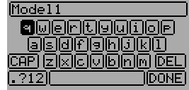
Model Name: Set the model’s name. Use the left, right, up, and down buttons then ENT to select each character.
Icon: Choose the model’s icon. Additional model icons can be installed (see USB & File-system).
Model Type: Set the model-type available options are Heli, Plane and Multi. Helicopter models have an additional configuration page that can be accessed by clicking the Model type. The options for SwashType are identical to the ones in Swash Configuration.
If you switch from model type Helicopter this will change the Mixer GUI to Advanced automatically because the Standard GUI only supports helicopters.
Transmitter Power: Specify the radio output power (when applicable). The valid power settings depend on the radio used by the selected protocol.
| CYRF6936, CC2500, MULTIMOD | 100µW, 300µW, 1mW, 3mW, 10mW, 30mW, 100mW, 150mW |
| A7105 | 100µW, 300µW, 1mW, 3mW, 10mW, 30mW, 100mW |
| NRF24L01 | 1mW, 6mW, 25mW, 100mW |
| R9M (PXX protocol) | 10/25mW, 100/25mW, 500/500, Auto/200 (FCC/EU) |
When changing the protocol in a model the power level will be set to the maximum for the radio used by the new protocol. Best to choose protocol first, then set Tx power.
Note: A stock Devo7e transmits with 7mW. Due to software configuration 150mW will always be displayed.
PPM In: Allows input from the DSC port primarily to control external hardware such as camera motors from a ‘head tracker’. Secondarily it may be used to enable the transmitter to act as a Master in a buddy-box setup. Available options are Channel, Stick and Extend.
The Stick and Channel modes are used for buddy-box setup and documentation can be found in chapter Setting up a Buddy-Box. The Extend mode is used for FPV or external input setup and documentation can be found in chapter Setting Up FPV or Other External Inputs.
Protocol: Set the type of receiver being used. Note that some protocols have additional options that can be accessed by pressing the Protocol spin-box when it is active. See section Protocols for more on specific protocols. Note that a protocol change will disable any currently active protocol and will affect any active model. To enable the newly chosen protocol, use the Bind/Re-Init button described below.
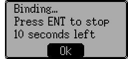
Bind/Re-Init: Depending on the protocol and Fixed-ID setting, the transmitter may bind with the model on start-up, or may need to be manually bound once. See Protocols for more on specific protocols. If the protocol does not support binding, the button will show ‘Re-Init’, which can be used to switch protocols without power-cycling the transmitter.
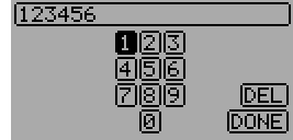
Fixed ID: The Fixed ID sets a unique code to ensure that the transmitter will only bind to a specific model. This is useful to ensure that the transmitter is not accidentally bound to the wrong model.
# Channels: Sets the number of channels to transmit (the maximum number of channels is dependent on the selected protocol).
9.1.1. Predefined Model Templates
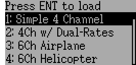
The Deviation firmware supports user-customizable predefined templates. By Selecting ‘Template…’ within the File spin-box from the Model page.
Additional templates can be added via USB to the ‘\template’ directory. A template does not completely replace your existing model, but instead only a portion of it. The currently supported templates will replace the mixer and trim definitions, but will not affect the display layout.
9.2. Mixer (Adv GUI)
The ‘Advanced’ GUI unleashes the full capabilities of the Deviation firmware, however it is unlike any commercial transmitter setup. Deviation also provides a more traditional setup interface for those who prefer it (see Standard GUI Menu items). With the Advanced GUI, each output channel is composed of a series of one or more mixers each of which consists of a single input, an activation switch, and a function/curve that modifies the mixer output. This is a very powerful capability, but it will require learning a completely different method for setting up a model. To aid in quick setup, there are a few predefined configurations available (see Predefined Model Templates), but to learn to modify and configure a model, read through this entire section carefully.
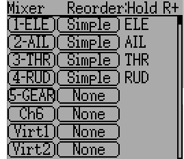
The Mixer page controls how inputs (sticks/switches) are assigned to output channels. The mixer page is accessed from the main menu by selecting the model icon..
The number of channels available is dependent on the number of channels selected in section Model setup (Std & Adv GUI). Additionally there are 10 Virtual channels that can be used as an intermediate step for complex setups.
9.2.1. Channel Reorder
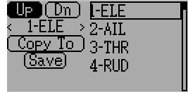
The Channel reorder page allows moving mixer definitions between channels as well as duplicating channel configurations. Note that the values displayed are the initial channel assignments. Whenever the page is loaded, the channels will be sequentially ordered representing the current state.
9.2.2. Channel configuration
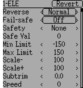
The Channel configuration provides the ability to configure the final channel outputs. Capabilities such as channel reverse and fail-safe values are applied here. Also available are controls for end-points, scaling, sub-trim, and a safety switch (which could be used to ensure that a motor cannot spin-up while working on a model)
Changes to this page will immediately effect the channel output. Pressing ‘Cancel’ will restore the shown values to their last saved state.
Reverse: Reverse the direction of servo rotation
Fail-safe: Specifies a value that the receiver should use when it loses signal from the transmitter. The range is between -125 and +125 or None. Not all receivers support this capability.
Safety: Specifies a switch that will override all mixers and force the channel output to ‘Safe Val’ when flipped.
Safe Val: If a safety switch is chosen the Safe Val can also be specified. The acceptable range of Safe Val is any value between -150 and 150.
Min Limit/Max Limit: These values define the minimum and maximum values that the transmitter will ever send to the receiver (after all scaling, trims and mixer are applied). If a calculated value is outside the min/max range, it will be clipped to either the min or max value as appropriate. Default is -150 for Min Limit and +150 for Max Limit. Maximum setting is -250 to 0 for Min Limit and 0 to 250 for Max Limit.
Scale-/Scale+: These values define a final scalar to adjust the servo throw. Allowed entries are between 1 and 250. When you alternate Scale+ Scale- will be changed in the same way. If Scale- has been set to a different value than Scale+ both data will act separately until you set them to the same value again.
Subtrim: Adjust servo zero position. The available range is between -50.0 and +50.0 in 0.1 increments.
Speed: Adjust maximum servo speed. Zero is disabled (fastest), Range is between 1 (slowest) and 250 (fastest). Servo speed is defined as number of degrees per 100msec (assuming a min/max throw of 120degrees).
Example: A value of 60 will give a speed of 60degrees per 100msec which is equivalent to center-to max in 100msec. Most servos are rated at ~60degrees/0.1sec, so a speed > 60 will have no affect on most servos. A value of 30 should be approx twice as slow as a typical servo.
9.2.3. Virtual channel configuration
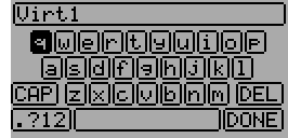
If you press ENT on a virtual channel a keyboard screen is shown where you may edit the default name. You can use L/R/UP/DN buttons followed by ‘ENT’ to select.
9.2.4. Simple Mix Type
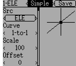
The Simple mix type is the simplest manner of defining a channel. It allows defining a primary-input (stick, switch, or other channel), and applying a curve or function to that input. The result can also be scaled or have an alternate zero-offset. You cannot use a toggle or switch to activate or deactivate this setup.
A ‘Long-ENT’ press will update the current mixer settings, making it possible to test them on the transmitter.
Src: The input source controlling this mixer.
Curve: The function applied to the input to generate the output. See section Available Curves for more info. Depending on curve-type, pressing curve may display the curve editor (see Curve Editing).
Scale: A multiplicative scalar that is applied after the Curve to control the output range.
Offset: An additive offset that is applied after the scaling.
9.2.5. Expo & Dual-Rate Mix Type
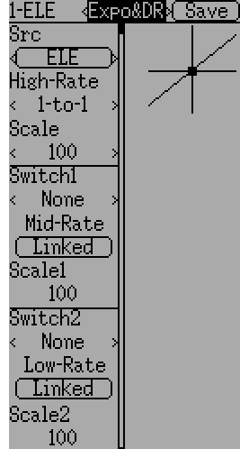
Selecting a value for Switch1 or Switch2 will activate the corresponding section. Each section can either have a ‘linked’ curve (curve is the same as the ‘High-Rate’ curve) in which case only the scalar can be modified, or alternatively can have an independent curve definition. Pressing the ‘Mid-Rate’ or ‘Low-Rate’ button for a given switch will toggle between linked and independent curves.
A ‘Long-ENT’ press will update the current mixer settings, making it possible to test them on the transmitter.
Src: The input source controlling this mixer.
Curve: The function applied to the input to generate the output. See section Available Curves for more info. Depending on curve-type, pressing curve may display the curve editor (see Curve Editing).
Switch1 or Switch2: Specify a switch to enable Medium or Low rates.
Scale: A multiplicative scalar that is applied after the Curve to control the output range.
9.2.6. Complex Mix Type
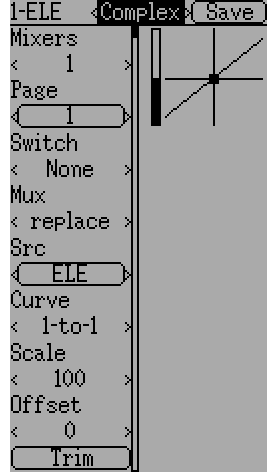
The Complex mix type unlocks the full power of the mixer system. For a given channel, any number of mixers can be applied to affect the final result. Each mixer is applied based on whether the specified switch is active, and can either replace, add to, or multiply to the previous mixers for this channel. Using this system it should be possible to define an output channel as a combination of any number of inputs.
A ‘Long-ENT’ press will update the current mixer settings, making it possible to test them on the transmitter.
The Complex Mixer page has the following options:
Mixers: Specify the number of mixers for this channel. If you increase the number a new mixer will be added after the last existing page.
Page: Specify the current mixer page being edited. Pressing the spin-box will allow reordering the pages of the current channel.
Switch: Specify an optional switch which determines whether the current mixer is active.
Mux: Defines how the current mixer is applied to the previously defined mixers for this channel. Options are:
- Replace: If this mixer is active, all previous mixers are ignored.
- Add: Add the value of this mixer to the previous mixers.
- Mult: Multiply the value of this mixer with the previous mixers. Note that the values are percentages, so multiplying by 50 actually multiplies by .5.
- Max: The output will be the greater of the current mixer vs the previous mixers.
- Min: The output will be the lesser of the current mixer vs the previous mixers.
- Delay: Delay the output of this mixer when used with a fixed curve. Scale of 100 represents 5 seconds delay. Can be varied by using scale or offset.
Src: The input source controlling this mixer.
Curve: The function applied to the input to generate the output. See section Available Curves for more info. Depending on curve-type, pressing curve may display the curve editor (see Curve Editing).
Scale: A multiplicative scalar that is applied after the Curve to control the output range.
Note that while the scale value is limited to 100%, the mixer may provide a value larger than 100% if an offset is set or if the trim value is non-zero.
Offset: an additive offset that is applied after the scaling.
Trim: Selects whether or not any trims for the selected source are applied to this mixer.
A given mixer can be considered to have the general form:
M(x) = if(Switch) { Src * Curve * Scale + Offset} else {0} + Trim
The combination of mixers for a given output channel is defined by the Mux type:
For a ‘Replace’ mux:
Cx = if(Switchn) {Mn} else if (Switchn-1) {Mn-1} … else if (Switch0) {M0}For a ‘Multiply’ mux:
Cx = if(Switchn) {Mn} else {1} * if (Switchn-1) {Mn-1} else {1} * … * if (Switch0) {M0} else {1}For an ‘Add’ mux:
Cx = if(Switchn) {Mn} else {0} + if (Switchn-1) {Mn-1} else {0} + … + if (Switch0) {M0} else {0}For a ‘Max’ mux:
Cx = MAX(if(Switchn) {Mn} else {0}, if (Switchn-1) {Mn-1} else {0}, …, if (Switch0) {M0} else {0})For a ‘Min’ mux:
Cx = MIN(if(Switchn) {Mn} else {0}, if (Switchn-1) {Mn-1} else {0}, …, if (Switch0) {M0} else {0})
9.2.7. Cyclic
Cyclic1, Cyclic2, Cyclic3: The 3 outputs of the helicopter swash-plate mix. These will represent the 3 servos connected to the helicopter swash-plate (see Swash Configuration).
9.2.8. Reordering Mixers
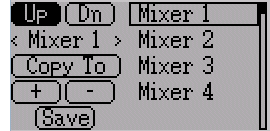
Select the respective mixer and use the up/down buttons to move the order of the selected mixer. Note that the mixer name represents its position when the reorder dialog was opened. If the dialog is closed and reopened, all mixers will be shown as numbered sequentially.
The reorder page can add new mixers or delete existing ones using the ‘+’ and ‘-’ buttons respectively. A mixer can also be copied to an existing mixer (overwriting it in the process) by using the ‘Copy To’ functionality.
9.2.9. Available Curves
The following curve functions are supported:
- 1-to-1: Output is equal to the input (not editable).
- Fixed: Output is constant regardless of input (offset editable).
- Min/Max: Output is -100 if input is less than the specified value and 100 otherwise.
- Zero/Max: Output is 0 if input is less than the specified value and 100 otherwise.
- >0: Output matches input when greater than the specified value, and 0 otherwise.
- <0: Output matches the input when less than the specified value, and0 otherwise.
- ABSVAL: Output is the absolute-value of the input (editing the specified value will alter how the absolute-value is applied)
- EXPO: Apply exponential curve to the input for non-linear response (editable see Curve Editing).
- Deadband: Output will not respond to input values near zero (editable see Curve Editing).
- Multi-point: Curve is based on 3, 5, 7, 9, 11 or 13 user-defined points (editable see Curve Editing).
The default value for any of the offsets in above mentioned curves is 0 (zero). If you change the curve for one input the offset will be transferred to the new curve if possible.
9.2.10. Curve Editing
The Curve Editor is accessed by selecting the curve spin-box when it is selectable. The 1-1 and Fixed curve types may not be edited, and the curve-box will not be selectable if one of these curves is currently active.
The Curve editor page will be different depending on which curve is selected. It is not possible to change the curve type from the curve editor (except when a multi-point curve is selected). Values can be set using the spin-box or by touching the graph.
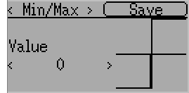
For the Min/Max, Zero/Max, >0, <0, and ABSVAL, the controls allow setting the transition point along the x-axis. A value of ‘0’ will be symmetric around the y-axis, positive or negative values will move the center point accordingly
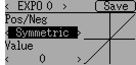
For the Expo curve, the controls allow independently configuring the shape of the curve for values greater-than or less-than zero.
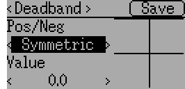
For the Deadband curve, the controls allow independently configuring the deadband width for values greater-than or less-than zero.
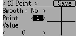
For the Multi-point curves, each point can be individually set. Points are set by choosing the point number and then choosing a value. The minimum number of points allowable is 3 the maximum number of points is 13. Enabling ‘Smooth’ will apply a smoothing function rather than connecting points via straight lines.
9.3. Timers (Std & Adv GUI)
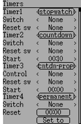
The timer page defines up to 4 available timers. Timers can count either up or down, and can be enabled either manually from the main screen or by an input trigger (stick or switch).
Available timers are stopwatch, countdown, stopwatch-proportional, countdown-proportional, and permanent.
Timers can also be optionally configured to be reset via an alternate switch (only when using the Advanced GUI).
Both proportional timers need an input between 0 and 100 to act correctly. If you use these timer for throttle a virtual mixer must be used as the input to scale -100 to 100 values into 0 to 100.
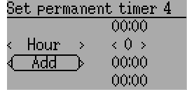
The ‘permanent’ timers are similar to an odometer and have their values saved in the model.ini file. They will maintain their previous value when powering up the transmitter. You can set the timer by using the ‘Set to’ button and reset by pressing the ‘Reset’ button.
9.4. Telemetry config (Std & Adv GUI)
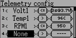
The telemetry configuration page allows specifying alarms when specific telemetry events occur.
- Telemetry: Specify the telemetry input to use for alarm control. The set of values available will depend on the protocol.
- Equality: Can be ‘>’ or ‘<=’ indicating whether a value above or below the target causes an alarm. Pushing the ENT button will play the alarm sound once.
- Target: The target value for the alarm. Additionaly, by pushing the ENT button you can cycle through a time delay (between 0 and 9 seconds) for which the target value has to be continuously reached before triggering the alarm.
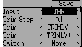
9.5. Trims and Virtual Inputs (Std & Adv GUI)
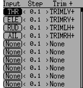
The trim page allows assigning the trim buttons and trim step, as well as configuring buttons to work as virtual inputs (see Using a Trim as a Virtual Switch). It is accessed from the main menu via ‘Model menu’ followed by ‘Trims’.
If the ‘Input’ field is set to an input stick, then the trim can be applied as part of the mixer, and will operate as a typical trim control. If the ‘Input’ field is set as a channel or virtual-channel output, the value is applied directly to the channel output. In this case, the selected ‘Trim +’ and ‘Trim -’ buttons can operate as a virtual stick to control an output channel.
The trim-step defines how sensitive the trims are to input. The maximum number of trim steps is +/-100. So a step size of 0.1 will allow a full +/- 10% of trim adjustment on the servo.
The trim-step can be changed on the main screen. If you have to change the source also please use the dialog accessed by pressing the respective ‘Input’ button. Here you may also add a switch to the trim. If a switch is added to the trim, then it will have different trim values in each switch position.
9.6. Datalog (Std & Adv GUI)
Note: This feature is not available for Devo7e.
The Datalog feature allows storing a history of input or output positions as well as telemetry info over a period of time. This can be used to examine and replay a flight as well as to visualize telemetry information at a later time. Logs are persistent and Deviation will continue writing to the end of the previous log by default.
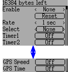
- # bytes left: Indicates how many bytes can be written to the log before it is full.
- Enable: Input which enables logging.
- Reset: Clear the current log.
- Rate: How often to write current info to the log file.
- Select: Quickly set or reset which items are logged.
- Controls: Following ‘Select’ are a list of all controls which may be logged. They include timers, inputs, outputs, and virtual channels, and Telemetry. The more items logged the faster the log will fill up.
Logging more information By default, the log can only store 16kB of data. You can increase the amount of data to be stored by changing the datalog.bin file on the transmitter to a larger size. Deviation cannot increase the size of this file, so its size indicates the maximum data that can be stored.
Note: This is a feature for advanced users only. There is currently no software provided to analyze the logs, and they cannot be visualized from within the transmitter. Please check the downloads section on www.deviationtx.com for conversion tools.
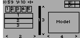
9.7. Main page config (Std & Adv GUI)
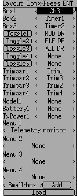
The main page config page is used to configure the main-page display. This page allows definition of which elements are shown on the main page.
The following types of objects can be displayed:
- Box: Display a numeric value. Values can be timers, channel values, stick inputs, etc. There are two types of boxes: big and small. The only difference is the size of the box and the text within it.
- Trimbar: Display a trim value. These generally are controlled by the trim switch and indicate what the current trim position is. There are two types of trims. V-Trims show a vertical bar, and H-Trims show a horizontal bar. After inserting all trims do have numbers only.
- Model (Icon): Display the icon related to the selected model.
- Battery: Display the battery voltage.
- TxPower: Displays the actual transmitter rating.
- Bargraph: Displays a vertical bar. The value of the bar is a channel output.
- Toggle: Show an icon indicating the state of a toggle switch. There can be 1, 2, or 3 icons defined for a given toggle indicating different states depending on the switch position. Two-state switches can have up to 2 icons. Three-state switches can have up to 3 icons.
- (Quick) Menus: Quick menus define quick-access pages that can be reached via a long UP/DN press.
9.7.1. Configuring object position
Note: This feature is not available for Devo7e.
Pressing and holding the ENT button from the model configuration page will switch to the object position screen. Each of the visual objects can be selected using the UP/DN buttons. Pressing ENT again will allow moving the placement of the selected object. The UP/DN/L/R buttons will move the selected object on the screen. Press EXT once to exit move mode, and again to go back to the main page config menu.
9.7.2. Creating Objects
Note: This feature is not available for Devo7e.
Select the object type from the spin-box on the left, then press ‘Add’ to create the object. This will add the relevant object type to the relevant section in the menu with a type of ‘None’ (where applicable). Then move the cursor to the newly created object and configure as desired.
9.7.3. Loading Objects
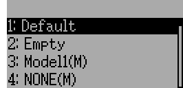
You can ‘Load’ alternate templates, to change the main page layout.
If you select ‘Default’ the layout will be set to the standard layout as shown in section Main Page.
Selecting ‘Empty’ will clear all objects. You may start from scratch.
If you want to use a layout from another model select the model whose layout you wish to use. The object positions (see Configuring object position) will be transferred when selecting from an existing template or model. Templates based on existing models have an (M) designation within the file list.
Additionally these templates can be created in the emulator or downloaded from the forums or even done by manual edit of the modelxx.ini file.
9.7.4. Configuring Objects
- Box: Select timer, telemetry, channel, or input from scroll-box
- Trim: Select trim channel from scroll-box
- Model: Not configurable
- Battery: Not configurable
- TxPower: Not configurable
- Bargraph: Select channel from scroll box
- Toggle: Select channel or input from scroll-box. Press related ‘Toggle’ button to choose icon
- Menu: Choose page to display for each of 4 quick-page slots
You can delete any object but a Menu page by selecting the ‘Delete’ option and pressing the ‘ENT’ button.
9.7.5. Choosing toggle icons
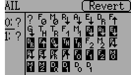
Pressing the ‘Toggle’ button on a toggle object allows selecting the related icons. Channels, sticks, and 2-position sticks can have 2 icons. 3 position sticks (if any) can have 3 icons. Each of the 2 (or 3) icon states can be set to empty, defining that no icon is shown for this state. The Deviation firmware comes with several predefined icons to choose from.
9.8. Standard GUI Menu items
- Model setup: Model configuration page (See section Model setup (Std & Adv GUI))
- Reverse: Servo reverse
- D/R & Exp: Dual-rates setup
- Subtrim: Servo sub-trim
- Travel adjust: Servo travel-adjust
- Throttle curves: Throttle curve setup
- Pitch curves: Pitch curve setup
- Throttle hold: Throttle-hold configuration
- Gyro sense: Gyro-sense configuration
- Swash: Swash Setup
- Fail safe: Fail-Safe configuration
- Switch assignment: Assign switch controls
- Timers: Timer configuration (See section Timers (Std & Adv GUI))
- Telemetry config: Configure telemetry alarms (See section Telemetry config (Std & Adv GUI))
- Datalog: Configure telemetry logging (See section Datalog (Std & Adv GUI))
- Main page config: Configure main page display (See section Main page config (Std & Adv GUI))
9.8.1. Servo Reverse
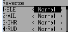
The servo reverse page allows quickly setting each channel to work in either normal or reversed mode. These settings are equivalent to the ‘Reverse’ setting on the Channel Configuration sub-page of the Mixer menu when using the Advanced GUI (see section Channel configuration)
9.8.2. Dual-Rate/Expo setting
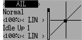
The dual-rate and expo page allows configuration of curves for the Aileron, Rudder, and Elevator channels. Up-to 3 rates can be configured for each channel, and either a scaled-linear or exponential curve can be selected for each. The number of settings depends on the switch assigned to the dual-rates function on the Switch Assignment page (see Switch Assignment)
9.8.3. Sub-trim Adjustment
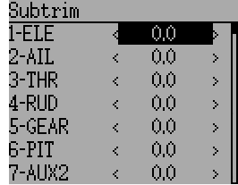
The sub-trim adjust page allows setting the zero-point of the servos for each channel. This is equivalent to the ‘Subtrim’ setting on the Channel Configuration sub-page of the Mixer menu when using the Advanced GUI (see Channel configuration). Acceptable values range from -50 to +50 in 0.1 increments.
9.8.4. Servo Travel Adjust
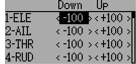
The servo-travel adjust page configures the maximum positive/negative travel of each servo. This is equivalent to the ‘Scale+’ and ‘Scale-’ settings on the Channel Configuration sub-page of the Mixer menu when using the Advanced GUI (see Channel configuration). Acceptable values for Down are from -175 to -1 and Up values range from +1 to +175. The default values are -100 and +100 respectively.
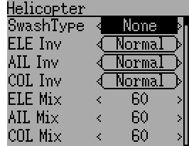
9.8.5. Swash Configuration
The Swash configuration page configures the swash type. More information about swash-types can be found in section Swash Mixing. The settings on this page are equivalent to those on the model configuration page (see Model setup (Std & Adv GUI)), and configuration for both pages is provided below.

The available SwashType values are:
- None/1Servo: Used For FBL. Mixing occurs in receiver
- 120/3Servo 120: 120-degree swash
- 120x/3Servo 120x: 120 degrees swash (alternate config)
- 140/3Servo 140: 140 degree swash
- 90/3Servo 90: 90 degrees swash
The ELE Mix, AIL Mix, and PIT Mix are scaling factors applied to the input sticks before mixing is done. These can be used to adjust for different linkage lengths or different servo throws. The allowed range is -100 to 100 with a default of 60. Note that setting these values too large can result in too much servo throw and make the model unresponsive to stick control.
9.8.6. Throttle Curve
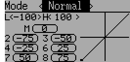
The throttle curve page allows defining a piece-wise linear curve for the throttle channel. Different curves can be selected for each flight-mode. Each point value can be enabled to be interpolated from the points surrounding it.
9.8.7. Pitch Curve

The pitch curve allows defining a piece-wise linear curve for the collective/pitch channel. Different curves can be selected for each flight-mode as well as for throttle-hold. Each point value can be enabled to be interpolated from the points surrounding it.
9.8.8. Gyro Sensitivity
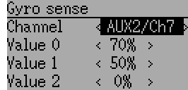
The gyro-sensitivity page enables configuring up-to 3 sensitivity values for the gyro as well as which channel to use for sending the gyro value. Acceptable values range from 0 to 100%.
9.8.9. Switch Assignment
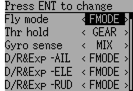
The switch assignment page enables configuring which switches to use for each capability in the standard-GUI. The same switch may be assigned to multiple capabilities.
9.8.10. Throttle Hold
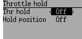
The throttle-hold page is used to enable/disable the throttle-hold capability. Specifying ‘Hold position’ defines the throttle value when the Throttle-hold switch is set. Hold position can be set from -200 to 200.
9.8.11. Fail-Safe Configuration
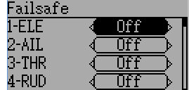
The fail-safe page is used to configure the fail-safe value for each channel (if the protocol supports this feature)