- Posts: 89
Wishlist for a custom Transmitter board
- Bisky
-
- Offline
Ultimate 7E + range mod + 3x2 switch mod + 3in1 module
Devo F7 XMS + 4in1 module
Please Log in or Create an account to join the conversation.
- phamminh
-
- Offline
- Posts: 20
Please Log in or Create an account to join the conversation.
- Fernandez
-
- Offline
- Posts: 983
www.banggood.com/1_54-Inch-E-ink-Screen-...ml?rmmds=newArrivals
Please Log in or Create an account to join the conversation.
- phamminh
-
- Offline
- Posts: 20
I think maybe we can use sh1106 1.3inch. but i'm getting 2 pixcel errors ,i can't fix it
Please Log in or Create an account to join the conversation.
- cody
-
- Offline
- Posts: 19
Please Log in or Create an account to join the conversation.
- phamminh
-
- Offline
- Posts: 20
Please Log in or Create an account to join the conversation.
- IeC
-
- Offline
- Posts: 3
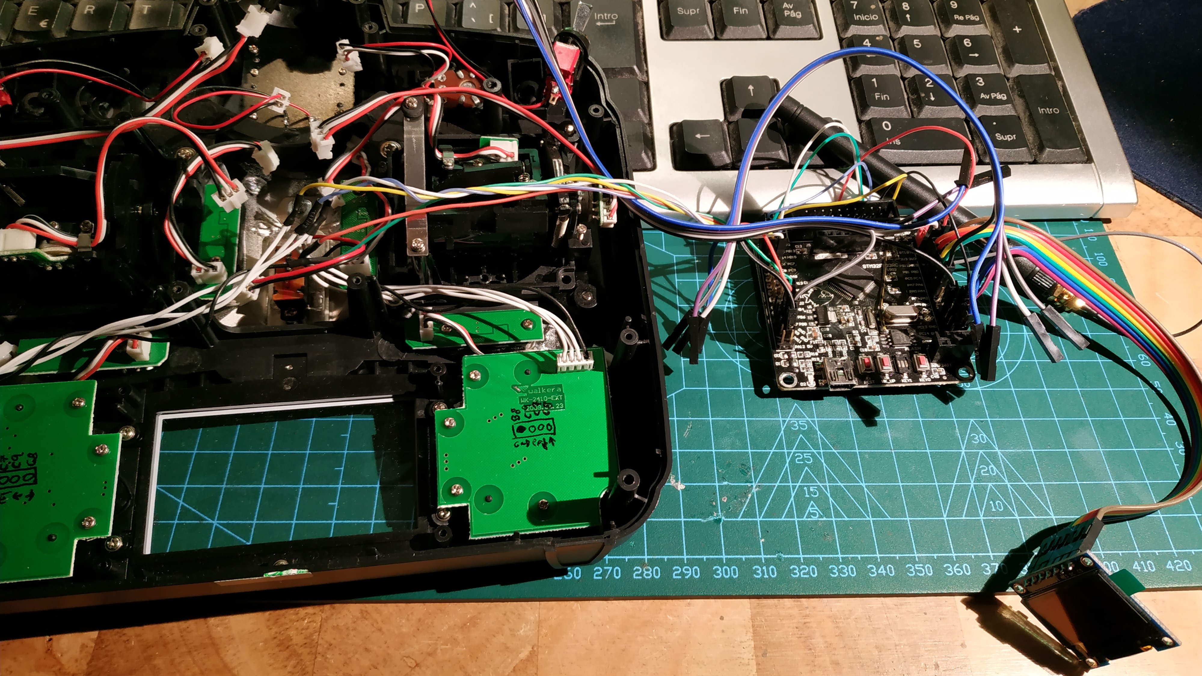
i appreciate a lot the work of all of you programming this great firmware. I como from Spain and i am now living in Germany. Here where i live i could buy for a couple of months an old Walkera transmitter (WK2403). I am trying to modify it with deviationtx. The development board that i am using ist based on the STM32F103RC. RF Modul ist the TI cc2500. I havent built the power circuit yet. I got everything working but the keys. The up Key is not working. I can only go down on the menus. I got the matrix scheme from the hardware wiki. What did i do wrong?
Thanks in advance.
Best regards,
IeC
Please Log in or Create an account to join the conversation.
- phamminh
-
- Offline
- Posts: 20
b6-c7 ent
b8-c9 ext
b8-c7 dow
b8-c8 up
b6-c8 R
b6-c9 L
Please Log in or Create an account to join the conversation.
- IeC
-
- Offline
- Posts: 3
thanks for the fast reply. I double checked the connections and are like you wrote. PA3 is connected to gnd. What else could it be? Coud i modify the model.ini in my computer to assign switches to channels to avoid using the keys? It wouldnt be really practical but as a solution solution could it work?
Thanks and best regards,
IeC
Please Log in or Create an account to join the conversation.
- phamminh
-
- Offline
- Posts: 20
Please Log in or Create an account to join the conversation.
- IeC
-
- Offline
- Posts: 3
Best regards,
IeC
Please Log in or Create an account to join the conversation.
- Eyolon
-
- Offline
- Posts: 13
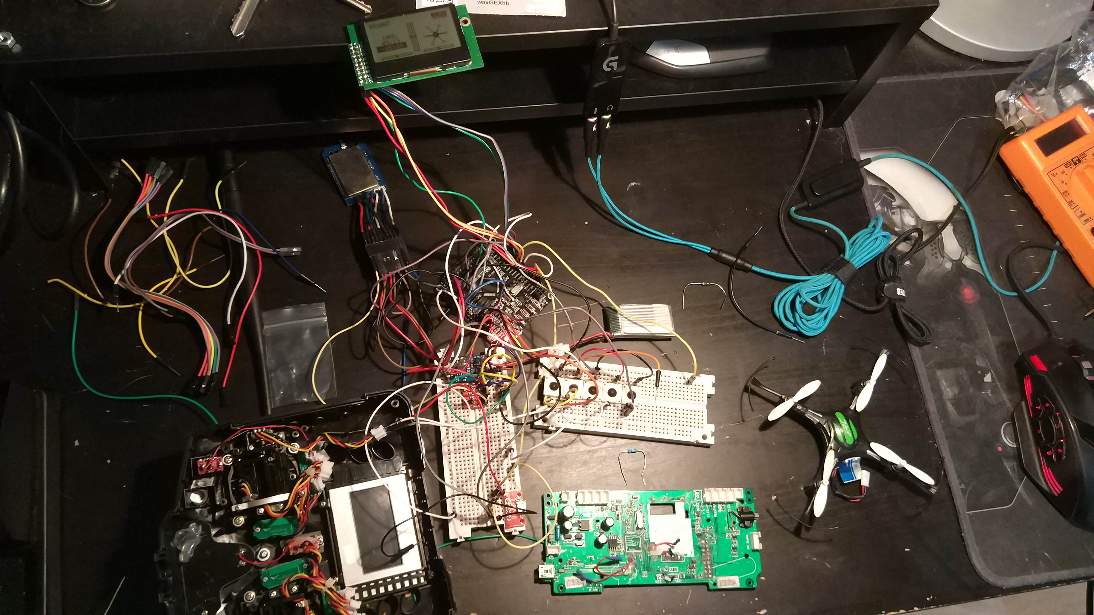
i wonder if i can use the original pcb with screen and buttons and connect it on the STM32F103RC board. What do you think of it ?
in second time, use the 4 in 1 module and finaly, use a cable inside to move the usb to external and work about use empty space.
Can i use wiring diagram of the Devo 7e to wire everything or i miss something ? and i've missunderstood : what firmware have you finaly used ? if i wire like the devo 7E can i use the devo 7 5.0.0 ?
Thank's for your answer, your custom-made rocks !
Please Log in or Create an account to join the conversation.
- Anugrah
-
- Offline
- Posts: 2
Please Log in or Create an account to join the conversation.
- Eyolon
-
- Offline
- Posts: 13
Any suggestion are welcome
Please Log in or Create an account to join the conversation.
- propnut
-
- Offline
- Posts: 172
Please Log in or Create an account to join the conversation.
- Eyolon
-
- Offline
- Posts: 13
Please Log in or Create an account to join the conversation.
- Fernandez
-
- Offline
- Posts: 983
You could also pinout some plugs for the 2 extra Pot's / ADC.
And or some extra switches. Possibly easiest to use the 7e 256 or Jumper T8SGV2. What display you'll use ?
Btw the RF module from your link is very expensive....You can buy even complete universal TX unit voor much less...
www.banggood.com/fr/URUAV-TMX5-4-IN-1-A7...10&cur_warehouse=USA
Please Log in or Create an account to join the conversation.
- Eyolon
-
- Offline
- Posts: 13
Today i've test my solution for power supply and it"s not enough (1S lipo with 10A45 to boost to 5V but it provide only 150-180mA) this night i'm going to test other clue in real situation.
Please Log in or Create an account to join the conversation.
- Eyolon
-
- Offline
- Posts: 13
The screen is the original, unsold from the original board.
And for extra you can make it done with the 10 pin (extension on rigth) providing 5V, 3v and unused (or not found on my wire plan :/) PC12 PA4-0-8 PB4-9-3
I ve solved my problem : one 10A45 for the buzzer and the board, another dedicated to the radio make it work during 4hours easily with 1S 850 mAh in not intensive use (model close and just switeched on)
i'll make change needed on my schema tomorrow and maybe add pins for a SSD1306 (i got one too) on back of the board, base the mapping on previous work
(CLK -> A.5
MOSI -> A.7
RESET -> B.1
D/C -> C.5
CS -> B.0)
at the end (in 2 or 3 day i guess) i send to my favorite factory (no joke, i frequently send my project there) and if it was a succes, release my project file (eagle format)
Attachments:
Please Log in or Create an account to join the conversation.
- Eyolon
-
- Offline
- Posts: 13
* some tests pad for pins i have no clue to use (but not supposed to be free)
* Power regulator place (AMS1117-5) to shutdown power of input charger (in back of the controller) it's for 12V max and used to supply. It require to not plug cathode battery to the pcb of the charger but directly to the pcb controller (by default it made common ground but it's not made for lipo after all)
* Adding pad to use DD0505MC ( ae01.alicdn.com/kf/HTB1XtyOKXXXXXaYaXXXq6xXFXXXc.jpg ) istead of sold it directly on the pcb (if you cant or just lazy but not crazy
* It's possibe to use a buildin plate to charge battery. You have place to glue it on the pcb
* Adding pin for SSD1302
* Adding cosmetic tag
Please Log in or Create an account to join the conversation.
-
Home

-
Forum

-
Development

-
Development

- Wishlist for a custom Transmitter board


