- Posts: 114
- Forum
- News, Announcements and Feedback
- Feedback & Questions
- Removing shield and diode 7E for better reach
Removing shield and diode 7E for better reach
- Mullson
-
Topic Author
- Offline
Here goes nothing: read before doing!
Read my first post, I am sorry I had to do it that way.
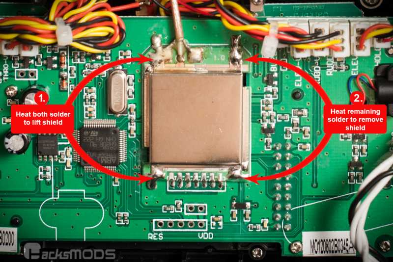
Get the module stable and have good lightening (you need some kind of solder holder board or something) to get away from any surface. Then use a wide pair of tweezers to get a grip of the shield, or drill some holes ore just something in-between in the opening of the corners.
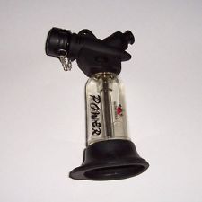
With the other hand light up your storm lighter (1300C).
Heat it on top in slow circular movements. With the exhaust point of the outer blue bounder(approximately 6-9s) depending on soldier flux and of course heat. You can use flux around the sides of the shield.
Suddenly it will just release, then lift it of in a confident move.
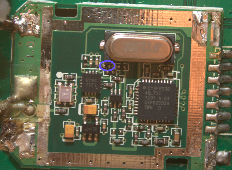
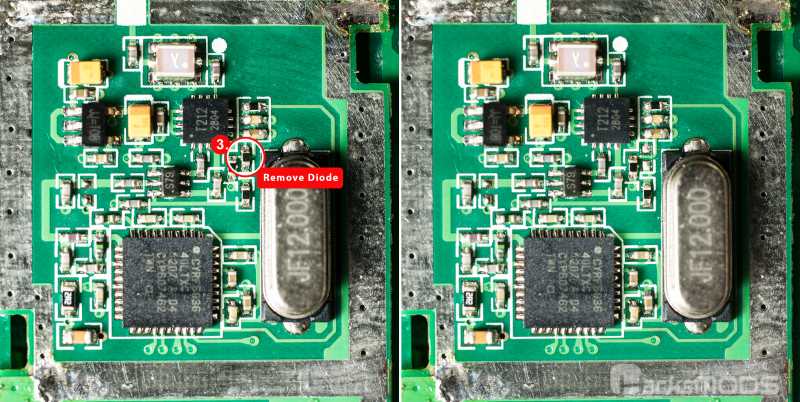
The diode:
This is PBs picture
Depending on your iron this is different. I will talk about how I did this low 18w. Probably would be better with 30 for this.
Get your iron clean (water and new solder), leave some. Get a pair of tweezers ready, and grab the diode. Put your rod to the point(fresh and with some solder on it) this will melt the old solder, lift it or slide it of.
When its removed there should be two small tin points.
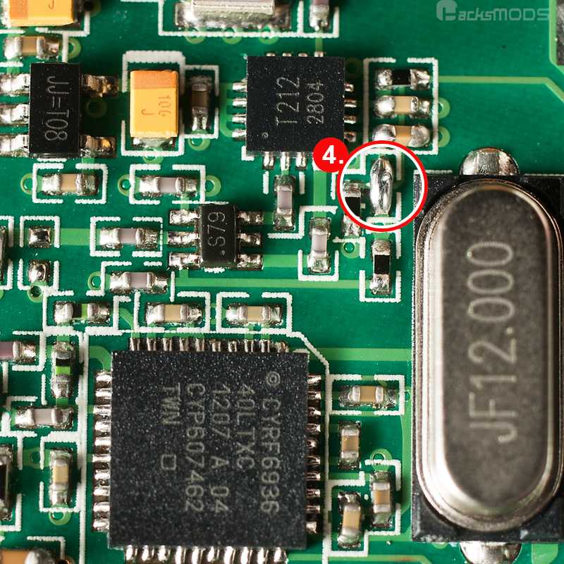
To shorten them put a small copper wire in between.
Tin your preferred wire shorten it and grab it with your tweezers. Place it and lightly tin your rod.
Let it touch the wire.
DONT FORGET TO PUT THE SHIELD BACK ON THE MODULE!
Clean module "or reuse the old solder. There is allot of it so I will use new" and solder the corners of the shield back on the module.
I can do a vid If there is a need.
Please Log in or Create an account to join the conversation.
- rbe2012
-
- Offline
- So much to do, so little time...
- Posts: 1433
Please Log in or Create an account to join the conversation.
- Mullson
-
Topic Author
- Offline
- Posts: 114
If so I would do it with glue "polyurethane" in the corners.
I tried to solder one back on and I wouldn't recommend doing it to something you need.
Do you think its necessary to have it on? If so why?
Please Log in or Create an account to join the conversation.
- PhracturedBlue
-
- Offline
- Posts: 4402
As far as I know the shield actually serves 2 purposes:
1) prevent unwanted radiation from the RF circuitry which could cause interference. the RF chips can radiate 2.4GHz radiation across the entire band (not the same as the output signals to the antenna), which could affect anything operating in the 2.4GHz band.
2) prevent the internal circuitry from picking up unwanted signals (preventing telemetry from working)
The shield acts as a faraday-cage and must be electrically-connected to the board otherwise it will have no significant effect, so using hot-glue or any other non-conductive contact will not be sufficient.
Please Log in or Create an account to join the conversation.
- RandMental
-
- Offline
- Posts: 521
BUT LET'S MAKE IT VERY CLEAR - YOU HAVE TO RE-SOLDER THE SHIELD BACK ON THE MODULE!
An open module WILL affect every 2.4GHz receiver around you and we shall make Deviation very unpopular with other RC enthusiasts if we start affecting their TX’s en R/C models the moment a Deviation transmitter is switched on. The same applies to using high TX power unnecessarily. (As we have it now 150mW and even 100mW are already way above what may be legally used in most countries on the 2.4GHz ISM band)
Let us not make Deviation the target of our fellow enthusiasts or the law.
Please Log in or Create an account to join the conversation.
- mmormota
-
- Offline
- Posts: 10
Please Log in or Create an account to join the conversation.
- Daryoon
-
- Offline
- Posts: 260
Short the two points to complete the circuit.
Blog post with the large photos. Feel free to use.
www.hacksmods.com/2013/04/walkera-devo-7...r-increase-range-mod
Please Log in or Create an account to join the conversation.
- RoGuE_StreaK
-
- Offline
- Posts: 486
(haven't done this yet, but this was how I read all the instructions to be; that's the power supply for the power amp?)
Please Log in or Create an account to join the conversation.
- thwaitm
-
- Offline
- Posts: 11
Please Log in or Create an account to join the conversation.
- old4570
-
- Offline
- Posts: 44
And if you wanted say only a 100 to 200% increase in output , what would be a good replacement diod ?
Please Log in or Create an account to join the conversation.
- RandMental
-
- Offline
- Posts: 521
With deviation you change or set the power output using the deviation software, not by using different diodes or voltages on this pin. (that is after doing the diode mod and enable the PA in the tx.ini file.)
Please Log in or Create an account to join the conversation.
- PhracturedBlue
-
- Offline
- Posts: 4402
To clarify RandMetal's point, this is an all or nothing thing. you can't use the diode to tune the power-output. with the diode the amp is off, with it shorted the amp is on; it isn't a volume control. The firmware is used to control the output power after applying the mod. If you use the stock firmware, you'll be transmitting at max power all the time, so don't do this if you are planning to go back to stock.old4570 wrote: Hmm , what is the value of the original diod ?
And if you wanted say only a 100 to 200% increase in output , what would be a good replacement diod ?
Please Log in or Create an account to join the conversation.
- RoGuE_StreaK
-
- Offline
- Posts: 486
Just to clarify, pic4 didn't exist before, it has been added recently. Props to Daryoon for the update.RandMental wrote: Pic 3 shows the diode removed, pic 4 shows the solder bridge.
Please Log in or Create an account to join the conversation.
- old4570
-
- Offline
- Posts: 44
PhracturedBlue wrote:
To clarify RandMetal's point, this is an all or nothing thing. you can't use the diode to tune the power-output. with the diode the amp is off, with it shorted the amp is on; it isn't a volume control. The firmware is used to control the output power after applying the mod. If you use the stock firmware, you'll be transmitting at max power all the time, so don't do this if you are planning to go back to stock.old4570 wrote: Hmm , what is the value of the original diod ?
And if you wanted say only a 100 to 200% increase in output , what would be a good replacement diod ?
Hmmm , so its all the way = Max Power + firmware change and then VIA firmware you can set output ?
Has their been any experiments yet with antenna swaps ?
Seems like the easiest option for a possible power ( range ) gain ..
Please Log in or Create an account to join the conversation.
- spiegel
-
- Offline
- Posts: 10
But the only problem is the frequency range so I decide to remove diode.
So please let me know how to edit tx.ini file.
Can it be edited simply by using notepad or is there any extra method?
Please Log in or Create an account to join the conversation.
- RandMental
-
- Offline
- Posts: 521
old4570 wrote: Has their been any experiments yet with antenna swaps ? Seems like the easiest option for a possible power ( range ) gain ..
Search the forum, we had a number of discussion on antenna replacement and it can help a bit - an increase of times 1.5 to 2 maximum.
Remember though that with x mW power going into the antenna, the only way to increase the radiated power is to focus it in specific directions. Simply put - what you gain in one direction you lose in other directions.
Please Log in or Create an account to join the conversation.
- rbe2012
-
- Offline
- So much to do, so little time...
- Posts: 1433
Editing with a simple text editor is fine, but you shouldn't use notepad because line wrapping does not work correctly there.spiegel wrote: Can it be edited simply by using notepad...
Use notepad++ or programmer's notepad instead (both freeware).
Please Log in or Create an account to join the conversation.
- spiegel
-
- Offline
- Posts: 10
rbe2012 wrote:
Editing with a simple text editor is fine, but you shouldn't use notepad because line wrapping does not work correctly there.spiegel wrote: Can it be edited simply by using notepad...
Use notepad++ or programmer's notepad instead (both freeware).
Thank you for your kind reply. I already solve it. RandMental let me know notepad++. But you guys really kind people. Thanks a lot.
Please Log in or Create an account to join the conversation.
- spiegel
-
- Offline
- Posts: 10
With my all thumbs soldering skill, I removed 4 diodes as the below picture. What can I do? Do I have to pay for another 7e or shorten 4 diodes?
Please Log in or Create an account to join the conversation.
- PhracturedBlue
-
- Offline
- Posts: 4402
I need to look over the circuitry to figure out your options.
You could always buy an 8S upgrade module (if they still sell them?) That is a reasonably easy install to replace the stock module (but you also need to get an antenna)
Please Log in or Create an account to join the conversation.
- Forum
- News, Announcements and Feedback
- Feedback & Questions
- Removing shield and diode 7E for better reach
-
Home

-
Forum

-
News, Announcements and Feedback

-
Feedback & Questions

- Removing shield and diode 7E for better reach

