
- Posts: 226
- Forum
- News, Announcements and Feedback
- Feedback & Questions
- How to build my Multi-Module..Project Is Complete!
How to build my Multi-Module..Project Is Complete!
- RedSleds
-
Topic Author
- Offline
Less
More
27 Apr 2015 19:21 - 19 Jun 2015 02:53 #31717
by RedSleds
DEVO 10 - Multi-module with nRF24L01 +PA +LNA, A7105 +PA, & CC2500 +PA +LNA transceivers.
Nightly Build: v4.0.1-548bbf5 (6/9/2015)
How to build my Multi-Module..Project Is Complete! was created by RedSleds
I am getting ready to build my Multi-Module, and trying to decide how to add the RF modules to the MM board. What I mean by that, is whether to solder the RF modules directly to the board using pins, or use headers and pins to make them removable by just unplugging them like SeBy DocKy did with his DEVO 10.
Advantages/disadvantages? Like, when using headers and pins to make them plug and unplug is there any appreciable voltage drop or any other downsides? Better reliability when soldered directly to the MM board? Etc.
I kind of like the idea of being able to unplug a module and swap it out if one fails, over having to desolder it from the board.
What are your thoughts???
DEVO 10 - Multi-module with nRF24L01 +PA +LNA, A7105 +PA, & CC2500 +PA +LNA transceivers.
Nightly Build: v4.0.1-548bbf5 (6/9/2015)
Last edit: 19 Jun 2015 02:53 by RedSleds.
- mwm
-
- Offline
01 May 2015 16:29 #31894
by mwm
Do not ask me questions via PM. Ask in the forums, where I'll answer if I can.
My remotely piloted vehicle ("drone") is a yacht.
Replied by mwm on topic Trying to decide on how to build my Multi-Module..
Since no one else answered, I'll say go with the sockets like SebyDocky does. It's possible that adding a new module will make an older one quit working, so taking them out to debug things isn't uncommon.
Do not ask me questions via PM. Ask in the forums, where I'll answer if I can.
My remotely piloted vehicle ("drone") is a yacht.
- RedSleds
-
- Offline
Less
More
- Posts: 226
18 Jun 2015 23:02 - 18 Jun 2015 23:58 #34331
by RedSleds
DEVO 10 - Multi-module with nRF24L01 +PA +LNA, A7105 +PA, & CC2500 +PA +LNA transceivers.
Nightly Build: v4.0.1-548bbf5 (6/9/2015)
Replied by RedSleds on topic Trying to decide on how to build my Multi-Module..
OK, got my DEVO 10 Mods all done. Here is my story..........
This isn't intended to be a “How-To-Build-One” guide about the Multi-Module and DEVO 10, it's just some pics, highlights, thoughts, and maybe some helpful ideas for somebody else to use on how I wound up doing the build of my DEVO 10.
CAUTION:
I did not use the same wire colors for each function that other builds on DeviationTx or some others that I found on the internet did, so be aware of that. I used a mix of wires that I got from Pololu and Banggood and assigned my own color scheme. So I won't be showing colored dots on the places where each wire connects, so as not to confuse anyone that is looking at DIY build tutorials.
I used SeByDocKy's video tutorial as the primary guide for my DEVO 10 Multi-Module modification/build, with a few changes that I implemented after thinking, and re-thinking, how I wanted to get it done. I must have watched it at least 20 times before I ordered the parts and tools that I needed to complete the project, ….and then watched it a few more times during the process too.
…..a big THANK YOU to SeByDocKy for making that vid!
I knew that I wanted to build the Multi-Module (MM) like he did, with all of the additional RF transceivers being able to be unplugged from the MM, and the MM itself also being able to unplug from the Tx. If one of the components ever goes bad, I will only need to solder header pins on the new part, unplug the bad one, and just plug in the new one without having to pull the whole works out of the Tx, de-solder, suck the remaining solder out of the corresponding holes, solder in the new component (and not have to worry about screwing something else up in the process), ...you get the picture.
This project is the first time that I have ever soldered such small things together, so the first thing that I did was to do a little research into how it should be done, watched some YouTube vids of how to, etc., etc. Be advised though, there are a lot of YouTube vids on soldering, and many are “experts” that don't know much of anything about the art of it all. But, I did manage to find a few that were done by bonafide professionals on the subject, and I shortened up my learning curve substantially.
Then I scrounged up an old PCB and practiced a bit on it until things turned out “not too bad” and sort of looked like I wouldn't do something stupid, like melt a hole through my DEVO. But then of course, I did have a few soldering troubles during my build, …..read on.
So, on with the project.
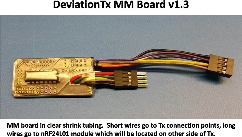
I soldered the lead wires on to the MM board that go out to the Tx. ...iron in contact with the joint for too long on a couple of them, melted insulation down the wire too far on the back side, and the alligator clip I used to hold everything in place while I soldered deformed the heat-softened insulation on the others :-/ Cut new wires and re-did. A new lesson to learn on how to wick solder out of the holes. Harder than it looked on YouTube, but got it done. New item on my Fry's Electronics shopping list: cheap, manual solder sucker.....Check!
Next item, solder two 2mm female headers to the MM, piece of cake! First one turned out great, ...until I tried to plug in the male pins. :-/ Solder had sucked into a couple of sockets on it. De-soldered the damned thing and used the new solder sucker to get excess solder out of those tiny holes, worked better than solder wick. Soldered in a fresh header, being extra careful, same result! Try a third time being extra-extra careful and checking each socket as I go, working great, ...until the tenth and last socket! Arrrrgghhh! Solder sucking was tedious with these smaller holes (and more of them) Thus, back to YouTube, and learned the “tapping molten solder out of holes” against the workbench technique. Works fast and easy, just be sure to wear goggles for this because you don't want to get molten solder back-splashed in your eyes! ...and maybe wearing shorts and no shirt isn't such a good idea either.
Started thinking about how to remedy my problem:
Then, as I was walking by my big roll-away toolbox in the garage, I spotted a piece of small diameter carbon fiber rod. Perfect! ….except it was 1mm and would not fit into the socket holes. Thus, a trip to the local hobby shop for some 0.8mm and 0.5mm carbon fiber rod. The 0.8mm did not fit, but the 0.5mm fit in sort of OK. I tried to use a diamond hone to make the 0.8mm rod into a square shape like the pins are, but did not have much success since I was getting impatient. Used the round 0.5mm rod, as-is, and it worked great! Success at last!!!
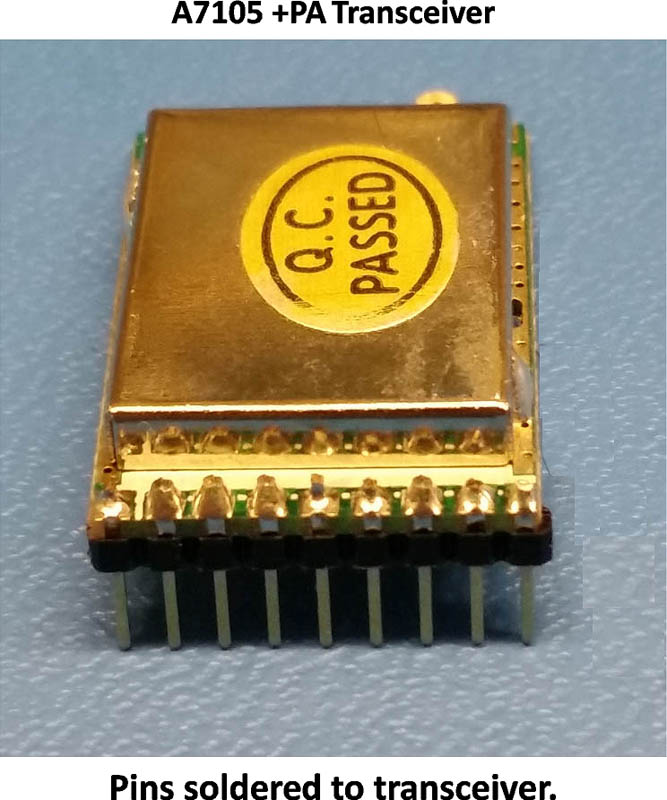
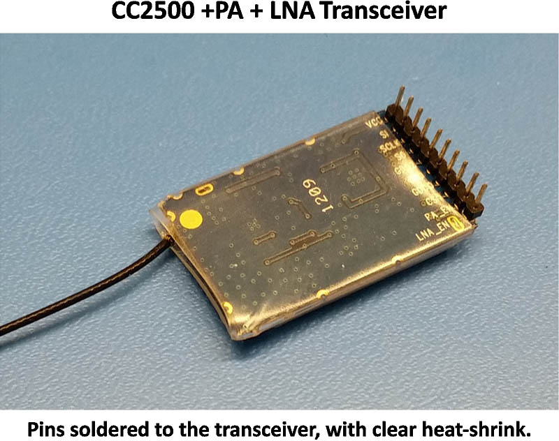
Then I soldered the corresponding pins to the CC2500 and XL7105/A7105 modules, piece of cake. As you can see from the following pics, I am not a soldering expert. …...yet, but they turned out good enough for the girls that I date. =O)
.
.
.
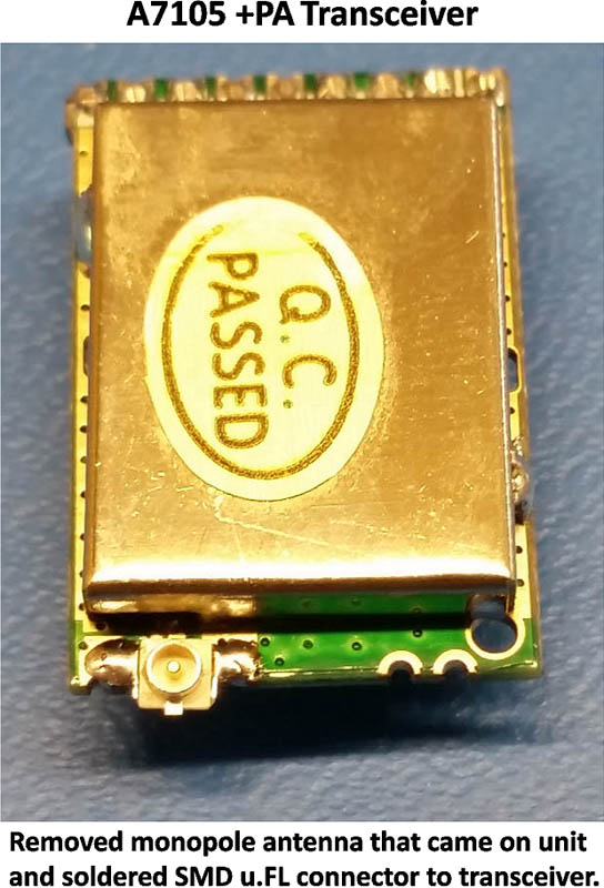
I removed the crummy antenna that came on the XL7105/A7105 and soldered on a SMD u.FL antenna connection because, well, just because I liked the idea of it instead of hacking up a coax antenna lead and making a fork out of the ground/shield wire & center conductor to solder to the 3 antenna points on the module.
Man, that u.FL thing is tiny!
.
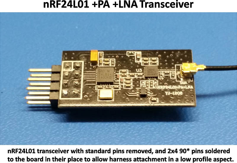
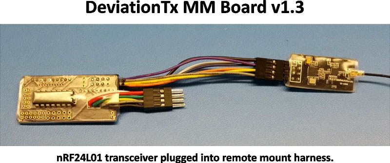
I decided to mount the nRF24L01 module remotely to keep the MM assembly a little smaller, since adding the headers made it substantially thicker than direct soldering the RF modules directly to it. So, soldered lead wires for it to the MM board, and removed the existing pins on the nRF24L01 and soldered on a 2.54mm 2x4x90* pin doohicky to it (yeah, that's a technical term) to make the connection a straight line instead of being at a right angle to the transceiver board.
.
.
.
.
.
.
This isn't intended to be a “How-To-Build-One” guide about the Multi-Module and DEVO 10, it's just some pics, highlights, thoughts, and maybe some helpful ideas for somebody else to use on how I wound up doing the build of my DEVO 10.
CAUTION:
I did not use the same wire colors for each function that other builds on DeviationTx or some others that I found on the internet did, so be aware of that. I used a mix of wires that I got from Pololu and Banggood and assigned my own color scheme. So I won't be showing colored dots on the places where each wire connects, so as not to confuse anyone that is looking at DIY build tutorials.
I used SeByDocKy's video tutorial as the primary guide for my DEVO 10 Multi-Module modification/build, with a few changes that I implemented after thinking, and re-thinking, how I wanted to get it done. I must have watched it at least 20 times before I ordered the parts and tools that I needed to complete the project, ….and then watched it a few more times during the process too.
…..a big THANK YOU to SeByDocKy for making that vid!
I knew that I wanted to build the Multi-Module (MM) like he did, with all of the additional RF transceivers being able to be unplugged from the MM, and the MM itself also being able to unplug from the Tx. If one of the components ever goes bad, I will only need to solder header pins on the new part, unplug the bad one, and just plug in the new one without having to pull the whole works out of the Tx, de-solder, suck the remaining solder out of the corresponding holes, solder in the new component (and not have to worry about screwing something else up in the process), ...you get the picture.
This project is the first time that I have ever soldered such small things together, so the first thing that I did was to do a little research into how it should be done, watched some YouTube vids of how to, etc., etc. Be advised though, there are a lot of YouTube vids on soldering, and many are “experts” that don't know much of anything about the art of it all. But, I did manage to find a few that were done by bonafide professionals on the subject, and I shortened up my learning curve substantially.
Then I scrounged up an old PCB and practiced a bit on it until things turned out “not too bad” and sort of looked like I wouldn't do something stupid, like melt a hole through my DEVO. But then of course, I did have a few soldering troubles during my build, …..read on.
So, on with the project.
I soldered the lead wires on to the MM board that go out to the Tx. ...iron in contact with the joint for too long on a couple of them, melted insulation down the wire too far on the back side, and the alligator clip I used to hold everything in place while I soldered deformed the heat-softened insulation on the others :-/ Cut new wires and re-did. A new lesson to learn on how to wick solder out of the holes. Harder than it looked on YouTube, but got it done. New item on my Fry's Electronics shopping list: cheap, manual solder sucker.....Check!
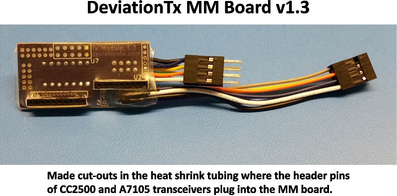
Next item, solder two 2mm female headers to the MM, piece of cake! First one turned out great, ...until I tried to plug in the male pins. :-/ Solder had sucked into a couple of sockets on it. De-soldered the damned thing and used the new solder sucker to get excess solder out of those tiny holes, worked better than solder wick. Soldered in a fresh header, being extra careful, same result! Try a third time being extra-extra careful and checking each socket as I go, working great, ...until the tenth and last socket! Arrrrgghhh! Solder sucking was tedious with these smaller holes (and more of them) Thus, back to YouTube, and learned the “tapping molten solder out of holes” against the workbench technique. Works fast and easy, just be sure to wear goggles for this because you don't want to get molten solder back-splashed in your eyes! ...and maybe wearing shorts and no shirt isn't such a good idea either.
Started thinking about how to remedy my problem:
- 1. Plug a strip of pins in the sockets, then solder the header to the MM? ….nope, rejected that solution in about half a second, they would get soldered securely into the sockets and would not be unplug-able at all.
- 2. Buy smaller gauge solder to be able to control how much gets fed to the joint? ….nope, I was using .031” diameter already, nothing smaller was available locally, and did not want to wait for some to show up via UPS or snail-mail.
- 3. Put something inside each socket that solder won't stick to, like plastic or wood? ….nope, plastic would melt, and wood would likely leave behind contaminants for a bad solder joint or just plain break off in the hole.
Then, as I was walking by my big roll-away toolbox in the garage, I spotted a piece of small diameter carbon fiber rod. Perfect! ….except it was 1mm and would not fit into the socket holes. Thus, a trip to the local hobby shop for some 0.8mm and 0.5mm carbon fiber rod. The 0.8mm did not fit, but the 0.5mm fit in sort of OK. I tried to use a diamond hone to make the 0.8mm rod into a square shape like the pins are, but did not have much success since I was getting impatient. Used the round 0.5mm rod, as-is, and it worked great! Success at last!!!
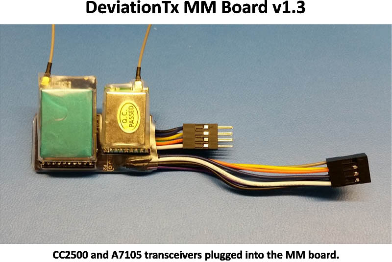
Then I soldered the corresponding pins to the CC2500 and XL7105/A7105 modules, piece of cake. As you can see from the following pics, I am not a soldering expert. …...yet, but they turned out good enough for the girls that I date. =O)
.
.
.
I removed the crummy antenna that came on the XL7105/A7105 and soldered on a SMD u.FL antenna connection because, well, just because I liked the idea of it instead of hacking up a coax antenna lead and making a fork out of the ground/shield wire & center conductor to solder to the 3 antenna points on the module.
Man, that u.FL thing is tiny!
.
I decided to mount the nRF24L01 module remotely to keep the MM assembly a little smaller, since adding the headers made it substantially thicker than direct soldering the RF modules directly to it. So, soldered lead wires for it to the MM board, and removed the existing pins on the nRF24L01 and soldered on a 2.54mm 2x4x90* pin doohicky to it (yeah, that's a technical term) to make the connection a straight line instead of being at a right angle to the transceiver board.
.
.
.
.
.
.
DEVO 10 - Multi-module with nRF24L01 +PA +LNA, A7105 +PA, & CC2500 +PA +LNA transceivers.
Nightly Build: v4.0.1-548bbf5 (6/9/2015)
Last edit: 18 Jun 2015 23:58 by RedSleds.
- RedSleds
-
- Offline
Less
More
- Posts: 226
18 Jun 2015 23:03 - 19 Jun 2015 00:01 #34332
by RedSleds
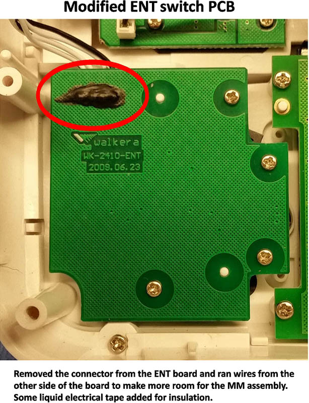
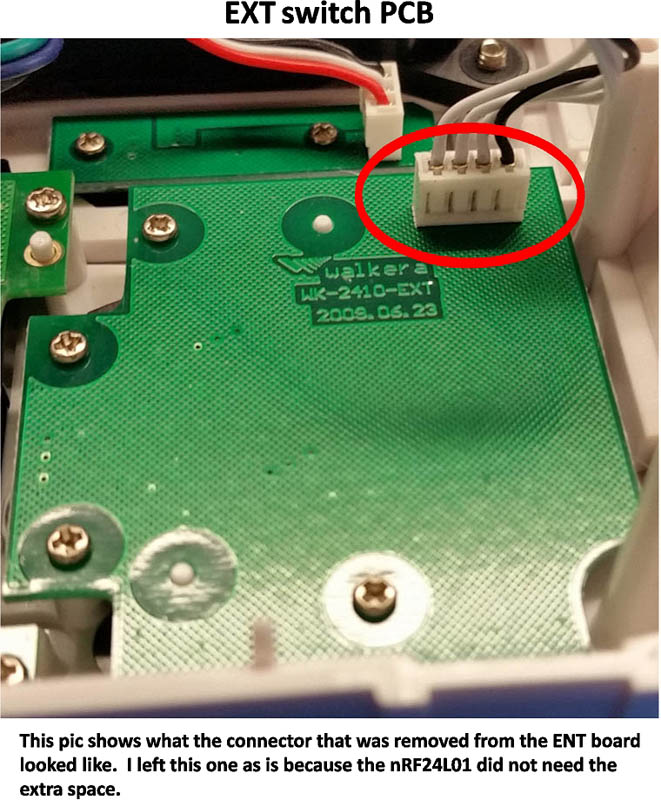
Also, to gain a little extra space for the MM, I re-did the wires going to the ENT switch by removing its header block and re-routing the wires from the other side of the ENT board. Maybe not necessary, but I did it anyway.
.
.
Now, we move on to the other part of the wire harness that connects to the main board of the Tx.
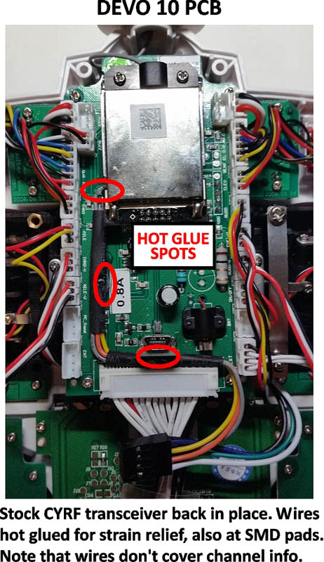
I elected to connect the SCK, MOSI, and MISO leads directly to the main board via the SMD pads on the header block of the stock CYRF module, instead of on top of the pins of the CYRF module itself.
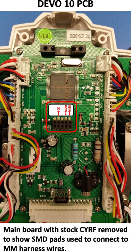
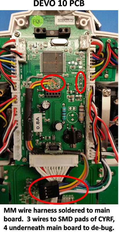
The following picture shows the harness soldered in place to the main board. The SCK, MOSI and MISO leads on top of the board, using heat-shrink tube to keep them neat and tidy, going to the CYRF SMD pads and hot glued in place. Note that I did not run them right up against the row of Tx connections so I could still read the designations for channel and switch plugs to the left side of the wires. The lower red circle is the 2x4 plug end that connects to the MM board.
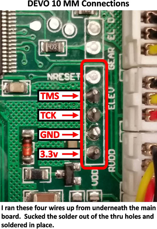
The TMS, TCK, GND, and 3.3v leads are routed under the main board and up into the de-bug port connection spots. I removed the main board to make this task easier to accomplish, but did not take any pics when it was out, as I was in the thick of it and didn't want to forget where everything was supposed to plug back in.
.
.
.
.
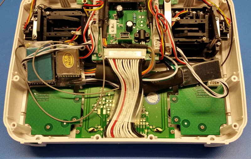
….and here is everything in its place, hooked up, and the Tx is all ready to be closed up!
.
DEVO 10 - Multi-module with nRF24L01 +PA +LNA, A7105 +PA, & CC2500 +PA +LNA transceivers.
Nightly Build: v4.0.1-548bbf5 (6/9/2015)
Replied by RedSleds on topic Trying to decide on how to build my Multi-Module..
Also, to gain a little extra space for the MM, I re-did the wires going to the ENT switch by removing its header block and re-routing the wires from the other side of the ENT board. Maybe not necessary, but I did it anyway.
.
.
Now, we move on to the other part of the wire harness that connects to the main board of the Tx.
I elected to connect the SCK, MOSI, and MISO leads directly to the main board via the SMD pads on the header block of the stock CYRF module, instead of on top of the pins of the CYRF module itself.
The following picture shows the harness soldered in place to the main board. The SCK, MOSI and MISO leads on top of the board, using heat-shrink tube to keep them neat and tidy, going to the CYRF SMD pads and hot glued in place. Note that I did not run them right up against the row of Tx connections so I could still read the designations for channel and switch plugs to the left side of the wires. The lower red circle is the 2x4 plug end that connects to the MM board.
The TMS, TCK, GND, and 3.3v leads are routed under the main board and up into the de-bug port connection spots. I removed the main board to make this task easier to accomplish, but did not take any pics when it was out, as I was in the thick of it and didn't want to forget where everything was supposed to plug back in.
.
.
.
.
….and here is everything in its place, hooked up, and the Tx is all ready to be closed up!
.
DEVO 10 - Multi-module with nRF24L01 +PA +LNA, A7105 +PA, & CC2500 +PA +LNA transceivers.
Nightly Build: v4.0.1-548bbf5 (6/9/2015)
Last edit: 19 Jun 2015 00:01 by RedSleds.
- RedSleds
-
- Offline
Less
More
- Posts: 226
18 Jun 2015 23:05 - 19 Jun 2015 02:44 #34333
by RedSleds
DEVO 10 - Multi-module with nRF24L01 +PA +LNA, A7105 +PA, & CC2500 +PA +LNA transceivers.
Nightly Build: v4.0.1-548bbf5 (6/9/2015)
Replied by RedSleds on topic Trying to decide on how to build my Multi-Module..
.
.

The project wasn't simple to do, but not terribly difficult either, thanks to a lot of great people here on the forums at deviationtx.com. I guess the steep learning curve (at least for me) of understanding the variables of deviation, how it all works, and how to make it do what I need it to do, is my next big challenge.
I'm glad that I went with the DEVO 10 instead of the 7E, I like the full size of it over the feel of a smaller Tx, and it makes flying my fleet of toy-grade quads so much better than with the little, dinky, Tx's that come with them. The improved range and response is the best thing though, no more signal drop-outs at the worst possible moment as you watch your toy quad drift off two neighborhoods away or get stuck 80 feet up in a tree. Well, ….not due to signal drop-outs anyway, those types of events will be all pilot error now! My flying has already improved quite a bit after using my deviated DEVO 10 for just a few sessions now. Looking forward to getting better and better this summer, and building a few brushless quads to fly before winter sets in.
I do have a plan to change the three internal antennae to external ones, but have a bit more cogitating to do on the plan, so it will most likely change a bit from what I currently am thinking it should look like and will be a while before I start on that. At the moment, I have the nRF24L01 transceiver hooked up to the external antenna, because that transceiver controls all of the quads that I have in my little fleet.
Thanks to everyone that helped me along the way!!!
…...now if you'll excuse me, I have some LIPO batteries to charge up. =O)
.
Ta Da!
The project wasn't simple to do, but not terribly difficult either, thanks to a lot of great people here on the forums at deviationtx.com. I guess the steep learning curve (at least for me) of understanding the variables of deviation, how it all works, and how to make it do what I need it to do, is my next big challenge.
I'm glad that I went with the DEVO 10 instead of the 7E, I like the full size of it over the feel of a smaller Tx, and it makes flying my fleet of toy-grade quads so much better than with the little, dinky, Tx's that come with them. The improved range and response is the best thing though, no more signal drop-outs at the worst possible moment as you watch your toy quad drift off two neighborhoods away or get stuck 80 feet up in a tree. Well, ….not due to signal drop-outs anyway, those types of events will be all pilot error now! My flying has already improved quite a bit after using my deviated DEVO 10 for just a few sessions now. Looking forward to getting better and better this summer, and building a few brushless quads to fly before winter sets in.
I do have a plan to change the three internal antennae to external ones, but have a bit more cogitating to do on the plan, so it will most likely change a bit from what I currently am thinking it should look like and will be a while before I start on that. At the moment, I have the nRF24L01 transceiver hooked up to the external antenna, because that transceiver controls all of the quads that I have in my little fleet.
Thanks to everyone that helped me along the way!!!
…...now if you'll excuse me, I have some LIPO batteries to charge up. =O)
DEVO 10 - Multi-module with nRF24L01 +PA +LNA, A7105 +PA, & CC2500 +PA +LNA transceivers.
Nightly Build: v4.0.1-548bbf5 (6/9/2015)
Last edit: 19 Jun 2015 02:44 by RedSleds.
- Richard96816
-
- Offline
Less
More
- Posts: 208
11 Jul 2015 19:40 #35342
by Richard96816
Replied by Richard96816 on topic Trying to decide on how to build my Multi-Module..
Thanks for the writeup. Well done.
My gut feeling (backed by a modicum of experience) is that building an antenna farm atop the transmitter is largely unnecessary. Unless you're using multiple signals simultaneously.
The antennas are just small wires inside plastic tubes. The tubes are just for esthetics and protection. Putting two or three wires into the same tube doesn't seem to hamper performance. At least when only one is energized at a time. Conversely, building a transmitter-top antenna farm is likely to create unwanted interactions. (And a fragile, unsightly mess.) Look up 'yagi' and 'parasitic elements'.
The better solution is finding a sturdy protective antenna tube with the features and dimensions of your choosing to contain all your antenna wires.
- RedSleds
-
- Offline
Less
More
- Posts: 226
11 Jul 2015 22:05 - 12 Jul 2015 10:33 #35344
by RedSleds

Thanks for the compliment. I think one thing that I forgot was a picture and description of the ATtiny24A-P microcontroller being soldered to the MM board, and the proper orientation of the component to the board, but then again, that has been covered elsewhere in many how-to tutorials.
As for multiple antennae in one tube, I don't think that there is really enough room in a standard antenna tube to fit four di-pole antennae inside, You would have to use a bigger diameter tube with enough clearance for four wires at the hinge point. Also, I would think that there would be some interference of wave propagation happening to which ever antenna happens to be physically behind other antennae wires. I guess one could custom make a flat antenna tube where they all were set side by side, with none in the shadow of another one in the direction of the model being flown.
Right now, the plan is to have two standard antennae (for the most frequently used RF transceivers) out of the top where the original one is, each pointing in opposite directions when bent to 90*. For the other two, at the moment, my thinking is to have RP-SMA ends come out from the back case with two short, unobtrusive mono-pole antennae to prevent feedback damage to the transceivers in case of accidentally activating them. Then when I do want to fly with one of those transceivers, I would remove the mono-pole antenna and attach a 90* 2.4gHz cloverleaf antenna. Either that, or attach a long di-pole antenna and rubber-band it on the top of one of the standard antenna tubes that is bent at a 90* angle. That way the Tx will not look too much like a porcupine with only two typical antennae sticking out the top and two relatively unnoticeable mono-pole antennae stuck to the back of the Tx.
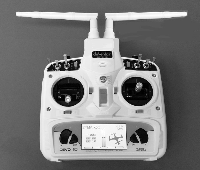
I'm still not done thinking about how to do it though. When I have time, I will Photoshop a mock-up to look at and see if that is what I really want to do, or not do. ...and so others can easier visualize what I mean.
Edit: A PS'ed mock-up of the front.....
Who knows, by the time I get it in gear, maybe the Single-Board Universal Module will be available and all this porcupine antenna dilema will become a moot point. Plug & Play, multiple transceiver, single antenna Tx, baby! w00t!!!
DEVO 10 - Multi-module with nRF24L01 +PA +LNA, A7105 +PA, & CC2500 +PA +LNA transceivers.
Nightly Build: v4.0.1-548bbf5 (6/9/2015)
Replied by RedSleds on topic How to build my Multi-Module..Project Is Complete!
Thanks for the compliment. I think one thing that I forgot was a picture and description of the ATtiny24A-P microcontroller being soldered to the MM board, and the proper orientation of the component to the board, but then again, that has been covered elsewhere in many how-to tutorials.
As for multiple antennae in one tube, I don't think that there is really enough room in a standard antenna tube to fit four di-pole antennae inside, You would have to use a bigger diameter tube with enough clearance for four wires at the hinge point. Also, I would think that there would be some interference of wave propagation happening to which ever antenna happens to be physically behind other antennae wires. I guess one could custom make a flat antenna tube where they all were set side by side, with none in the shadow of another one in the direction of the model being flown.
Right now, the plan is to have two standard antennae (for the most frequently used RF transceivers) out of the top where the original one is, each pointing in opposite directions when bent to 90*. For the other two, at the moment, my thinking is to have RP-SMA ends come out from the back case with two short, unobtrusive mono-pole antennae to prevent feedback damage to the transceivers in case of accidentally activating them. Then when I do want to fly with one of those transceivers, I would remove the mono-pole antenna and attach a 90* 2.4gHz cloverleaf antenna. Either that, or attach a long di-pole antenna and rubber-band it on the top of one of the standard antenna tubes that is bent at a 90* angle. That way the Tx will not look too much like a porcupine with only two typical antennae sticking out the top and two relatively unnoticeable mono-pole antennae stuck to the back of the Tx.
I'm still not done thinking about how to do it though. When I have time, I will Photoshop a mock-up to look at and see if that is what I really want to do, or not do. ...and so others can easier visualize what I mean.
Edit: A PS'ed mock-up of the front.....
Who knows, by the time I get it in gear, maybe the Single-Board Universal Module will be available and all this porcupine antenna dilema will become a moot point. Plug & Play, multiple transceiver, single antenna Tx, baby! w00t!!!
DEVO 10 - Multi-module with nRF24L01 +PA +LNA, A7105 +PA, & CC2500 +PA +LNA transceivers.
Nightly Build: v4.0.1-548bbf5 (6/9/2015)
Last edit: 12 Jul 2015 10:33 by RedSleds.
- FDR
-
- Offline
12 Jul 2015 16:46 #35373
by FDR
Just think about the yagi antennas, which consists of a dipole and a few passive reflectors...
Replied by FDR on topic Trying to decide on how to build my Multi-Module..
I have to admit, that I don't remember too much of what I had learned about antenna systems, but they told us that every piece of conductive material affects the radiation pattern, even the passive ones.Richard96816 wrote: ...Putting two or three wires into the same tube doesn't seem to hamper performance. At least when only one is energized at a time...
Just think about the yagi antennas, which consists of a dipole and a few passive reflectors...
- SeByDocKy
-
- Offline
Less
More
- Posts: 1016
12 Jul 2015 18:36 #35377
by SeByDocKy
Replied by SeByDocKy on topic How to build my Multi-Module..Project Is Complete!
Excellent job ") Cleaner job that I did
Cleaner job that I did ")
- aMax
-
- Offline
Less
More
- Posts: 776
12 Jul 2015 18:42 #35378
by aMax
Devo7e, TaranisQ X7, R9M , 4in1 MM, Futaba FC18plusV3.2 & DFT/FLD-02
Replied by aMax on topic How to build my Multi-Module..Project Is Complete!
Simply put a coaxial termination dummy load on each of the sockets at the back and if needed , swap it with one of the existing antennas.RedSleds wrote:
Right now, the plan is to have two standard antennae (for the most frequently used RF transceivers) out of the top where the original one is, each pointing in opposite directions when bent to 90*. For the other two, at the moment, my thinking is to have RP-SMA ends come out from the back case with two short, unobtrusive mono-pole antennae to prevent feedback damage to the transceivers in case of accidentally activating them.
Devo7e, TaranisQ X7, R9M , 4in1 MM, Futaba FC18plusV3.2 & DFT/FLD-02
- RedSleds
-
- Offline
Less
More
- Posts: 226
12 Jul 2015 19:39 #35380
by RedSleds
Could even use 3 of the dummies, and only need to have 1 antenna out the top of the Tx.
DEVO 10 - Multi-module with nRF24L01 +PA +LNA, A7105 +PA, & CC2500 +PA +LNA transceivers.
Nightly Build: v4.0.1-548bbf5 (6/9/2015)
Replied by RedSleds on topic How to build my Multi-Module..Project Is Complete!
Hmmm......., now there is a good plan!aMax wrote: Simply put a coaxial termination dummy load on each of the sockets at the back and if needed , swap it with one of the existing antennas.
Could even use 3 of the dummies, and only need to have 1 antenna out the top of the Tx.
DEVO 10 - Multi-module with nRF24L01 +PA +LNA, A7105 +PA, & CC2500 +PA +LNA transceivers.
Nightly Build: v4.0.1-548bbf5 (6/9/2015)
- Richard96816
-
- Offline
Less
More
- Posts: 208
12 Jul 2015 20:31 #35381
by Richard96816
Proper circuitry would not allow multiple transceivers to be activated in the first place.
Replied by Richard96816 on topic How to build my Multi-Module..Project Is Complete!
... unobtrusive mono-pole antennae to prevent feedback damage to the transceivers in case of accidentally activating them.
Proper circuitry would not allow multiple transceivers to be activated in the first place.
- RedSleds
-
- Offline
Less
More
- Posts: 226
12 Jul 2015 21:07 #35382
by RedSleds
DEVO 10 - Multi-module with nRF24L01 +PA +LNA, A7105 +PA, & CC2500 +PA +LNA transceivers.
Nightly Build: v4.0.1-548bbf5 (6/9/2015)
Replied by RedSleds on topic How to build my Multi-Module..Project Is Complete!
No, but it is possible to mistakenly select, activate, and transmit with a transceiver that does not have an antenna attached to it. .....not a good thing.
DEVO 10 - Multi-module with nRF24L01 +PA +LNA, A7105 +PA, & CC2500 +PA +LNA transceivers.
Nightly Build: v4.0.1-548bbf5 (6/9/2015)
- Forum
- News, Announcements and Feedback
- Feedback & Questions
- How to build my Multi-Module..Project Is Complete!
Time to create page: 0.394 seconds
-
Home

-
Forum
-
News, Announcements and Feedback
-
Feedback & Questions
- How to build my Multi-Module..Project Is Complete!