
- Posts: 4403
Single-Board Universal Module
- PhracturedBlue
-
Topic Author
- Offline
Less
More
14 Sep 2014 21:47 #25664
by PhracturedBlue
Replied by PhracturedBlue on topic Single-Board Universal Module
One of the boards has obviously bad manufacturing (missing traces etc). The other 2 (including the one I built) look ok visually. I had a bunch of bridges on the mcu after reflow. I think that is probably because I bumped it halfway through and had to re-place it. I thought I'd created the short there, but after cleaning up all the bridges, it was still there. So I really don' know.
Somewhat related, I have never in my life been able to properly use solder wick. I've seen people use it just fine, but I can't remove solder with it either on through-hole parts or to fix bridges. I made a mess of the mcu trying to fix the bridges with it (lifted a pad, made things worse). While I eventually got the bridges fixed using my hot-air gun, in the end I just removed the mcu and cleaned up the pads, but the short is still there.
Somewhat related, I have never in my life been able to properly use solder wick. I've seen people use it just fine, but I can't remove solder with it either on through-hole parts or to fix bridges. I made a mess of the mcu trying to fix the bridges with it (lifted a pad, made things worse). While I eventually got the bridges fixed using my hot-air gun, in the end I just removed the mcu and cleaned up the pads, but the short is still there.
- PhracturedBlue
-
- Offline
Less
More
- Posts: 4403
14 Sep 2014 21:48 #25665
by PhracturedBlue
Replied by PhracturedBlue on topic Single-Board Universal Module
Which DRCs are you referring. I don't see any violations using the 4-layer rules for OSH Park (note that their 4-layer and 2-layer rules are not the same)
- mikemacwillie
-
- Offline
Less
More
- Posts: 152
14 Sep 2014 22:06 - 14 Sep 2014 22:07 #25667
by mikemacwillie
Replied by mikemacwillie on topic Single-Board Universal Module
I'm using the 4 layer rules from here:
support.oshpark.com/support/articles/400...10-eagle-design-rule
which seem to agree with the 5 mil trace and space and 4mil annular ting rules on their specs page. I get 140 errors, with about ~1/3 of them clearance. Make sure the layers are visible, or they don't show up in the DRC list. A whole bunch of the other DRC errors are just library issues and can be approved. I don't really think this is the cause of the power to ground short though. They're all clearance between a via and a pad of the same signal.
I see lots of people remove too much solder from surface mount pads with solder wick while cleaning up bridges. It's also really easy to overheat and lift pads while using it. There are some hollow shaped chisel tips for the Hakko iron I have that are great for removing excess solder and cleaning up bridges. They have a little bowl in the flats of the chisel, which holds on to the solder. I'm not sure what iron you have, but it might be worth looking for something similar for your iron.
I see lots of people remove too much solder from surface mount pads with solder wick while cleaning up bridges. It's also really easy to overheat and lift pads while using it. There are some hollow shaped chisel tips for the Hakko iron I have that are great for removing excess solder and cleaning up bridges. They have a little bowl in the flats of the chisel, which holds on to the solder. I'm not sure what iron you have, but it might be worth looking for something similar for your iron.
Last edit: 14 Sep 2014 22:07 by mikemacwillie.
- PhracturedBlue
-
- Offline
Less
More
- Posts: 4403
14 Sep 2014 23:41 #25671
by PhracturedBlue
Replied by PhracturedBlue on topic Single-Board Universal Module
I have a chinese temperature controlled iron with hot air gun. But it'll fit hakko tips. I'll take a look.
I have all relevant layers turned on, and the only DRC violations I see are on the stop-mask layer. We actually designed to more conservative rules than OSHPark requires so that the board can be made at Chinese PCB shops.,
Did you grab the latest board from:
bitbucket.org/SadSack/universaltx-4-layer
The logo should reference 'UniveralTx-0.9'
- mikemacwillie
-
- Offline
Less
More
- Posts: 152
15 Sep 2014 02:00 #25674
by mikemacwillie
Replied by mikemacwillie on topic Single-Board Universal Module
Yeah, I have the 0.9 layout. I wonder if maybe we have different restring values, causing the annular ring on the vias to be larger for me. If you have no DRC errors, I'm sure the problem is on my end.
- mikemacwillie
-
- Offline
Less
More
- Posts: 152
15 Sep 2014 02:41 #25675
by mikemacwillie
Replied by mikemacwillie on topic Single-Board Universal Module
Found it.. The DRC rules used on the layout in the repository have 0 mil minimum for same signal clearance. Not a huge issue, but that explains why we were getting different DRC results.
- victzh
-
- Offline
Less
More
- Posts: 1386
15 Sep 2014 16:58 #25684
by victzh
Replied by victzh on topic Single-Board Universal Module
PhracturedBlue, what microscope do you use? How does it compare with glasses?
- PhracturedBlue
-
- Offline
Less
More
- Posts: 4403
15 Sep 2014 21:09 #25687
by PhracturedBlue
Replied by PhracturedBlue on topic Single-Board Universal Module
I have one of these:
www.amscope.com/microscopes/3-5x-180x-st...th-80-led-light.html
I've been using it for a couple years and prefer it over the other options I've tried
a) I can hook it up to a monitor
b) Using the 0.5X Barlow, it has a 8" working distance
c) It has a great field of view
c) The LED ring gives excellent illumination
I have only compared it to cheap binocular glasses and a jeweler's loupe (and of course a stationary magnifying glass). I get less eye-strain and much better control and working distance with the scope than I had with any of the above.
I'm actually about to upgrade the head to a trinocular scope. Dropping a camera into the eyepiece when I want a monitor is annoying. I'm just trying to decide if I should upgrade to the ZM head or not.
One thing about cameras. Most cheap ones have a tiny sensors which narrows the field of view (giving unwanted extra magnification). I prefer either a DSLR or a large-sensor astronomy camera to get a full frame image.
- mikemacwillie
-
- Offline
Less
More
- Posts: 152
20 Sep 2014 00:15 #25740
by mikemacwillie
Replied by mikemacwillie on topic Single-Board Universal Module
Well, another week and no boards for me.  Hopefully they show up next week.
- moss
-
- Offline
Less
More
- Posts: 40
24 Sep 2014 14:09 - 24 Sep 2014 18:28 #25788
by moss
Replied by moss on topic Single-Board Universal Module
Nice project!
I just did a pull from bitbucket.org/SadSack/universaltx-4-layer/downloads and looked at the schematic. (june 3, 2014)
The DRU still comes up as a 2-layer board?
EDIT: I just pulled V0.9 which has 4 layers. This is not the typical stack-up which has ~9mil dielectric on outer layers.
9 mil dielectric is doable for FR4 keeping 50 ohm lines at sane widths.
(strip-line should be 14 mil wide on 8 mil FR4 ~ e=4.4)
The 1.5 mm dielectric would make those 9 mil lines 133 Ohm.
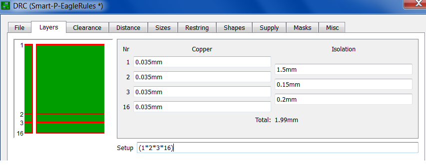
This would be a typical mass production type board, 1oz. outer, 1/2oz. inner copper and ~ 8 mil dielectric.
Just quickly breezing tru schematic for possible trouble, and I saw one that bit me once;
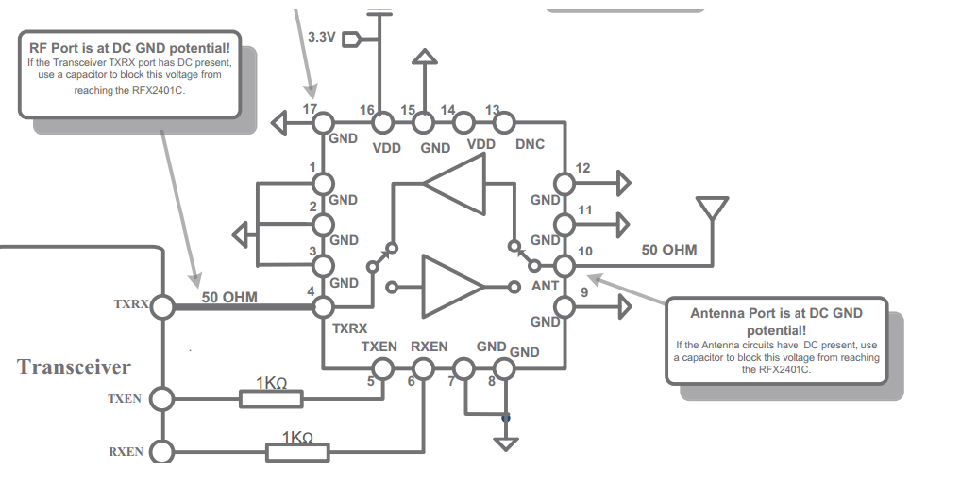
The SKY13384-350LF U6 pin 15 input as well as the RFX2401C U5 pin4 are both have DC, and there is no DC-blocking cap on this line. Odds are the DC-levels are not the same. The other ports on the 4-way switch have DC-blocking via the matching caps, which should suffice. The RFX2401C has DC on antenna, and to reduce chances for mishaps a cap here would not hurt.
The SMT USB connectors are not as robust as the thru hole type, H2960TR-ND. The strength of copper adhesion to the FR4 is not that impressive.
Did you consider a SAW filter on the PA input? You get a 2dB loss, but your harmonics will be way down, the filter takes out ~ 40dB out band stuff.
The 3x3 mm filters are easy to use, the smaller ones are a bit hairy.
The pi-filter (band-pass) on the antenna is not very effective, and has a 2dB loss with ideal components. A simple low value cap (3pF NPO ~0.08dB S21 at 2.4GHz) ) may be enough to cut out lower frequency stuff, and block DC.
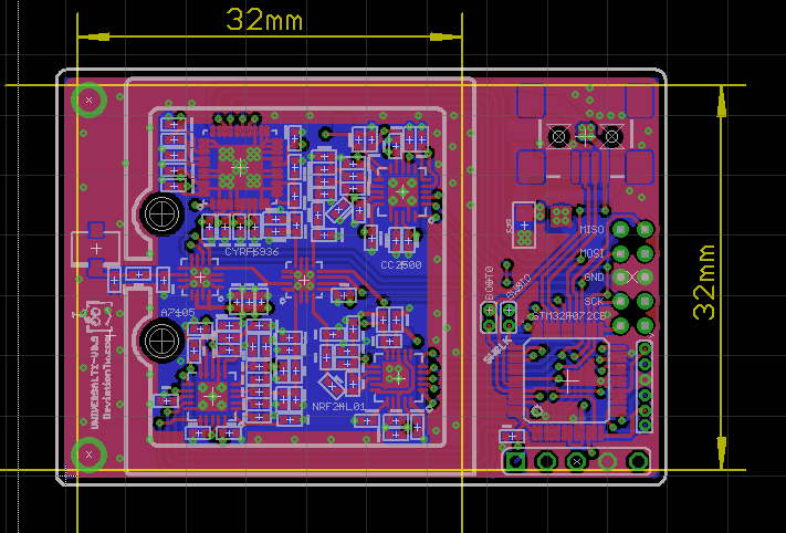
Bypass caps on the PA chip could be closer, the lowest value cap here at least. Why not pour ground around the whole top? More ground vias is better, too many is not possible!
Cream layer shows no paste under PA.
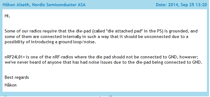
The nRF24L01 has a metal slug, I think this needs to be soldered in too, but the mfg. should perhaps be asked.
It is hard to inspect solder under the chips (w/o x-ray) but more solder would not hurt, the excess will be sucked out in the vias.
I just did a pull from bitbucket.org/SadSack/universaltx-4-layer/downloads and looked at the schematic. (june 3, 2014)
EDIT: I just pulled V0.9 which has 4 layers. This is not the typical stack-up which has ~9mil dielectric on outer layers.
9 mil dielectric is doable for FR4 keeping 50 ohm lines at sane widths.
(strip-line should be 14 mil wide on 8 mil FR4 ~ e=4.4)
The 1.5 mm dielectric would make those 9 mil lines 133 Ohm.
This would be a typical mass production type board, 1oz. outer, 1/2oz. inner copper and ~ 8 mil dielectric.
Just quickly breezing tru schematic for possible trouble, and I saw one that bit me once;
The SKY13384-350LF U6 pin 15 input as well as the RFX2401C U5 pin4 are both have DC, and there is no DC-blocking cap on this line. Odds are the DC-levels are not the same. The other ports on the 4-way switch have DC-blocking via the matching caps, which should suffice. The RFX2401C has DC on antenna, and to reduce chances for mishaps a cap here would not hurt.
The SMT USB connectors are not as robust as the thru hole type, H2960TR-ND. The strength of copper adhesion to the FR4 is not that impressive.
Did you consider a SAW filter on the PA input? You get a 2dB loss, but your harmonics will be way down, the filter takes out ~ 40dB out band stuff.
The 3x3 mm filters are easy to use, the smaller ones are a bit hairy.
The pi-filter (band-pass) on the antenna is not very effective, and has a 2dB loss with ideal components. A simple low value cap (3pF NPO ~0.08dB S21 at 2.4GHz) ) may be enough to cut out lower frequency stuff, and block DC.
Bypass caps on the PA chip could be closer, the lowest value cap here at least. Why not pour ground around the whole top? More ground vias is better, too many is not possible!
Cream layer shows no paste under PA.
The nRF24L01 has a metal slug, I think this needs to be soldered in too, but the mfg. should perhaps be asked.
It is hard to inspect solder under the chips (w/o x-ray) but more solder would not hurt, the excess will be sucked out in the vias.
Last edit: 24 Sep 2014 18:28 by moss.
- PhracturedBlue
-
- Offline
Less
More
- Posts: 4403
24 Sep 2014 20:15 #25792
by PhracturedBlue
Replied by PhracturedBlue on topic Single-Board Universal Module
Thanks for the feedback. If you read through this thread, you'll find I have no experience working on RF designs, and this is my 1st attempt at it. So there's bound to be lots of stuff that got done wrong/could be improved.
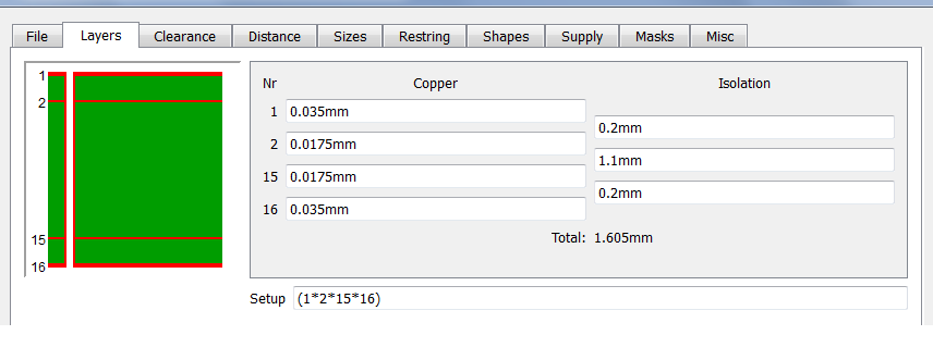
We didn't necessarily adjust the stack-up, since it doesn't affect the gerber files. The stackup is whatever the manufacturer uses (in the case of oshpark 6.7/47/6.7 but the board tolerances should allow it to be produced on many manufacturers process) The line widths should be pretty close to 50 ohm if I calculated it properly.
It is a good point on the dc blocking caps, but I wouldn't have a clue how to go about sizing them.
I am aware of the missing solder mask below the mux and PA chips. I only found that after getting the stencils back, but it'll be fixed in the next iteration.
We were running out of room on the board, and I'm not sure a through-hole usb port will hold. I am well aware the SMT ones are less robust, but the USB port won't get a lot of use in normal operation. It is worth looking at again though.
The pi filter on the antenna came directly from the rfaxis docs (or maybe app note) as a means to help with FCC compliance (should I ever get that far). I'm not confident enough in what I'm doing to try to design it myself. The same goes for a SAW filter.
The nrf manual specifically recommends not to solder the pads, so I didn't.
If you are interested to help, I'd be glad for it. As I said above, I'm basically flying blind. Sadly we don't yet have a functional board to even verify functionality much less measure RF performance.
- moss
-
- Offline
Less
More
- Posts: 40
24 Sep 2014 20:48 - 25 Sep 2014 12:52 #25793
by moss
Replied by moss on topic Single-Board Universal Module
The DC blocking cap can be almost any value, just big enough to not attenuate the RF, 3 - 100pF should do. You can probably cut the trace and scrape off some solder-mask with an X-acto blade and shoe-horn a cap in the TX-line.
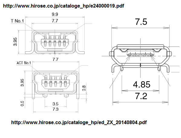
The thru hole USB may take less room than the one you now have. Micro USB is becoming more common, phones and stuff, and may save you some space. It can be hand soldered on the "other" side too.
I did not catch the shield mfg. but Digi-Key has those good'n cheap Laird parts with removable lid. the 32x32mm 903-1053-1-ND could work if you moved the RF connector to the "other" side, the 1x1" may be too tight.
I found the harmonics filter in the app note www.bocon.com.cn/artupfile/2013-12-24/02013122401460816545.pdf
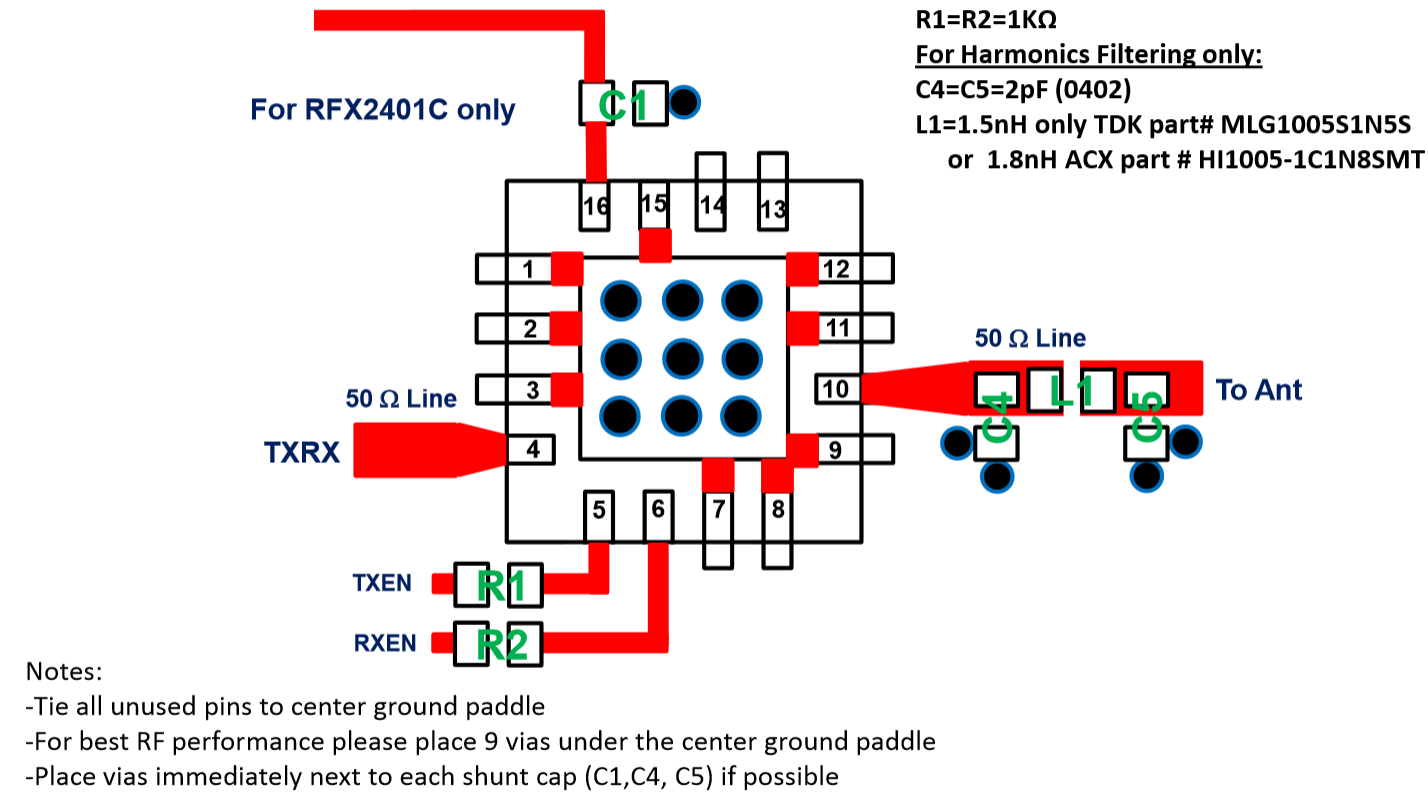
www.mouser.com/ds/2/400/DEA162450BT-1288B1-269740.pdf probably better than the discretes, ~ 1 dB loss.
Any plans to include FASST?
Nordic Semi answered that grounding of the center pad is not necessary, nor possibly harmful:-)
The thru hole USB may take less room than the one you now have. Micro USB is becoming more common, phones and stuff, and may save you some space. It can be hand soldered on the "other" side too.
I did not catch the shield mfg. but Digi-Key has those good'n cheap Laird parts with removable lid. the 32x32mm 903-1053-1-ND could work if you moved the RF connector to the "other" side, the 1x1" may be too tight.
I found the harmonics filter in the app note www.bocon.com.cn/artupfile/2013-12-24/02013122401460816545.pdf
www.mouser.com/ds/2/400/DEA162450BT-1288B1-269740.pdf probably better than the discretes, ~ 1 dB loss.
Any plans to include FASST?
Nordic Semi answered that grounding of the center pad is not necessary, nor possibly harmful:-)
Last edit: 25 Sep 2014 12:52 by moss.
- PhracturedBlue
-
- Offline
Less
More
- Posts: 4403
25 Sep 2014 13:36 #25801
by PhracturedBlue
Replied by PhracturedBlue on topic Single-Board Universal Module
I don't have any FASST raidos to work on the protocol.
That is good to hear from the nordic folks. It would allow using a Belkin transciever as a replacement as it is drop in compatible pin wise (there would still be a change in BOM, as the balance network would need to be tweaked)
Becasue of the mounting restrictions on the Walkera radios, I don't think I can place the antenna on the bottom of the board. I was also tryingto avoid any vias on the RF signal.
I never got far enough to plan for a shield box. But it is definitely worth looking into if there are off-the-shelf boxes that can be made to fit.
- moss
-
- Offline
Less
More
- Posts: 40
25 Sep 2014 14:54 - 25 Sep 2014 18:10 #25802
by moss
Replied by moss on topic Single-Board Universal Module
The FAAST receiver I have here uses a
www.rfmw.com/PortalPartSearch.aspx?txtSearch=ML2730
chip. It may already be "old".
I don't have a SPI bus analyzer so can't give you any dumps, but I'm interested to see how the "bind" works. Is it usually, or always, a two way hand shake? I would think the TX GUID is visible in the receiver SPI data stream? In one case the frequency hopping table was an algorithm based on this, but I guess it also could be a programmed look-up table or a dump from the transmitter?
I'm thinking of getting a Salae SPI bus analyzer, but they are not currently shipping,(new models underway) is that the one to get?
The PCB could use some more vias, the output connector grounds will be more robust with vias, The PA chip in the app note has more vias (9), likely for thermal reasons. Cram in as many as you can.
A shield can around the TX may not be necessary, it is often included as an option in case you get into trouble.
Last edit: 25 Sep 2014 18:10 by moss.
- PhracturedBlue
-
- Offline
Less
More
- Posts: 4403
25 Sep 2014 20:54 - 25 Sep 2014 20:54 #25804
by PhracturedBlue
Replied by PhracturedBlue on topic Single-Board Universal Module
I have a Saleae Logic, and I really like it. Also, when I had problems, their support was excellent. there are knockoffs that perform just as well for a fraction of the price, but I have no experience with them, and can absolutely recommend Saleae as a company.
I don't have experience with the ML2730. Futaba has a bunch of different protocols, using a couple different chips. I was thinking of the CYRF6936 variant. One of the problems with the ML2730 as I recall is obtaining them can be challenging.
I have one board left to try to assemble. After that we'll need to make another run.
I've made some of the changes you recommended: Moved PA vias, added DC blocking, added a few more vias, added a paste layer under the mux and PA. I added another via under the PA, but to go more than 5 will violate the DRCs I'm using on drill spacing. I did not try to add a SAW filter, or adjust the Harmonics filter. I didn't switch to a through-hole USB either, as I can't find a micro-usb through-hole, and I already have a bunch of the ones currently speced in stock. As far as a top-pour goes, I've tried before, and I'm not happy with how it turns out. Maybe I'm just not very good at controlling Eagle, I don't know.
Last edit: 25 Sep 2014 20:54 by PhracturedBlue.
- vlad_vy
-
- Offline
Less
More
- Posts: 3333
26 Sep 2014 10:10 #25812
by vlad_vy
Replied by vlad_vy on topic Single-Board Universal Module
About Futaba 18MZ tx module (ML2724 + CC2500)
www.deviationtx.com/forum/3-feedback-que...utaba-s-binding#2289
www.deviationtx.com/forum/3-feedback-que...utaba-s-binding#2289
- moss
-
- Offline
Less
More
- Posts: 40
26 Sep 2014 19:23 - 26 Sep 2014 19:48 #25816
by moss
Replied by moss on topic Single-Board Universal Module
mini USB thru-hole will save a little space, if needed, and micro USB thru hole even more.
Approximate board areas, 47 mm^2 micro TH, 71 mm^2 mini TH, and 89 mm^2 for mini SMT.
www.digikey.com/product-detail/en/ZX62D-.../H11610CT-ND/1963859
Approximate board areas, 47 mm^2 micro TH, 71 mm^2 mini TH, and 89 mm^2 for mini SMT.
www.digikey.com/product-detail/en/ZX62D-.../H11610CT-ND/1963859
Last edit: 26 Sep 2014 19:48 by moss.
- mikemacwillie
-
- Offline
Less
More
- Posts: 152
26 Sep 2014 20:28 #25817
by mikemacwillie
Replied by mikemacwillie on topic Single-Board Universal Module
Personally, I don't think the surface mount USB connector is a bad choice. They're strong enough given how infrequently it's used on this module, they're quite easy to source, and if this ever gets mass produced, they can be placed for reflow soldering. That corner of the board isn't particularly busy, so the smaller footprint isn't really an issue.
- mikemacwillie
-
- Offline
Less
More
- Posts: 152
27 Sep 2014 03:32 #25825
by mikemacwillie
Replied by mikemacwillie on topic Single-Board Universal Module
Well, my boards arrived today. One of them has a power to ground short like yours, but the other two appear okay.. We shall see.
I got the top side mostly populated this evening. I ran in to one issue... I have no idea where I put the damn PAs when they arrived. They weren't in my bin with the rest of the parts. I went ahead and populated the top side anyways.. I'll use my hot air gun to place the PA when (if) I find them. I've ordered more just in case I accidentally threw them out with the pile of packaging.
Here's one fresh off the hot plate. I prefer the hot plate to the oven for this kind of thing; The only trade-off is you can't reflow a double sided board with it. I had planned on doing the back side by hand anyways. They turned out fairly well, only a few spots will need touchup. There are a couple of solder joints that are a bit dry due to having vias in the pads, which wicks away the solder. Easy enough to touch up.

Overall, they go together quite easily. It's nice to see that you didn't use the built-in 0402 footprint from Eagle, which has pads that are a little bit too big and far apart for good reflow. I'll look at cutting the trace and adding the DC blocking cap when I do the touch up.
I got the top side mostly populated this evening. I ran in to one issue... I have no idea where I put the damn PAs when they arrived. They weren't in my bin with the rest of the parts. I went ahead and populated the top side anyways.. I'll use my hot air gun to place the PA when (if) I find them. I've ordered more just in case I accidentally threw them out with the pile of packaging.
Here's one fresh off the hot plate. I prefer the hot plate to the oven for this kind of thing; The only trade-off is you can't reflow a double sided board with it. I had planned on doing the back side by hand anyways. They turned out fairly well, only a few spots will need touchup. There are a couple of solder joints that are a bit dry due to having vias in the pads, which wicks away the solder. Easy enough to touch up.
Overall, they go together quite easily. It's nice to see that you didn't use the built-in 0402 footprint from Eagle, which has pads that are a little bit too big and far apart for good reflow. I'll look at cutting the trace and adding the DC blocking cap when I do the touch up.
- PhracturedBlue
-
- Offline
Less
More
- Posts: 4403
27 Sep 2014 14:03 #25827
by PhracturedBlue
Replied by PhracturedBlue on topic Single-Board Universal Module
Nice. I really like how one person's 'complete pain in the butt' turns into someone else's 'quite easily' ")
Even without the PA, you can power up the boards (once you've got the reverse side built). The test code will verify that the RF chips are talking on the SPI bus properly.
I have a test dfu file here:
dl.dropboxusercontent.com/u/52854517/universaltx_DOA.dfu
The code is in the main deviation depo (under the universaltx dir)
I never actually finished the code to interface it with the radio, so at the moment it can't do much more than write out status on the stdout pin. I currently have PPM (JP2 pin 1) configured for stdout.
The stm32f072 has a built-in USB bootloader. To enable it, you should place a jumper across BOOT0. This jumper places the stm32 into bootloader mode when power is applied by USB (but not by normal 5V supply). If you plan to use a 5V supply to the 10-pin header, you can leave the jumper in place. The jumper is there so that the board can optionally be used as a USB controlled radio (maximizing its utility)
Just install the STM DFuSe tool:
www.st.com/web/en/catalog/tools/FM147/CL...C961/SS1533/PF257916
Then start the software, and plug in the board via USB (without 5V power attached). DFuSE should detect the board if everything goes smoothly. Then just 'Upgrade' the dfu file (make sure not to do an 'Upload' since that is actually a download and exactly the opposite of what you want)
JP2.1 is the debug output. Hook it up via a USB2UART at 115200,N,8,1
If everything goes really well, it will output:
Power Up
NRF24L01: Found
A7105: Found
CC2500: Found
CYRF6936: Found
Done
Time to create page: 1.999 seconds
-
Home

-
Forum
-
Development
-
Development
- Single-Board Universal Module