
- Posts: 4403
Single-Board Universal Module
- PhracturedBlue
-
Topic Author
- Offline
Less
More
26 May 2014 23:42 #23644
by PhracturedBlue
Replied by PhracturedBlue on topic Single-Board Universal Module
Well, I wired up the STM32F072 discovery board to the NRF PAEN and PA TX/RX, and it seems to work well.
The nrf only enables VDD_PAEN during transmit (elsewise is is off) My crude code takes 5.1us to switch the PA (should be easy enough to improve that), and the PA seems to be doing its thing (range was acceptable)
So I now know:
a) I can program the STM32F072
b) the circuit seems to be working ok to enable the ACK on the NRF24L01
- SadSack
-
- Offline
Less
More
- Posts: 317
27 May 2014 01:28 - 27 May 2014 01:29 #23646
by SadSack
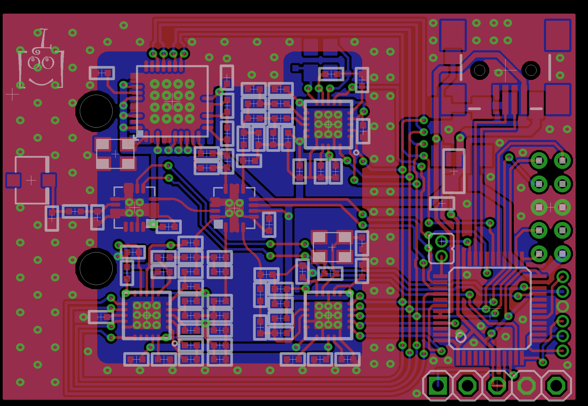
Going slow but fun")
Replied by SadSack on topic Single-Board Universal Module
Going slow but fun
Last edit: 27 May 2014 01:29 by SadSack.
- victzh
-
- Offline
Less
More
- Posts: 1386
27 May 2014 03:17 #23650
by victzh
Sounds great! You had a productive Memorial Day!
Replied by victzh on topic Single-Board Universal Module
PhracturedBlue wrote: So I now know:
a) I can program the STM32F072
b) the circuit seems to be working ok to enable the ACK on the NRF24L01
Sounds great! You had a productive Memorial Day!
- SadSack
-
- Offline
Less
More
- Posts: 317
27 May 2014 03:39 #23651
by SadSack
Any thoughts Good or Bad ?
I'm open to fresh ideas...
Replied by SadSack on topic Single-Board Universal Module
Any thoughts Good or Bad ?
I'm open to fresh ideas...
- PhracturedBlue
-
- Offline
Less
More
- Posts: 4403
27 May 2014 04:29 #23656
by PhracturedBlue
SadSack has been going to town on the board design. he's got it looking much nicer than how I left it. I justwish we knew what we were doing with regards to this 2.4GHz stuff
I have learned a lot about Smith charts in the past week or so. I now understand how the matching devices work for the most part. But (a) there are parasitic effects that are not documented that need to be considered, and (b) Not all data-sheets document the driving impedance of the RF circuitry. So while I understand how it works, I can't actually figure out how to tweak the components to account for the discrepancies we may have added
Replied by PhracturedBlue on topic Single-Board Universal Module
I did not have much fun soldering the leads onto the NRF module. Removing the switch was trivial, but soldering wires to 0402 pads was not fun. My hands just aren't steady enough. Using a pair of helping hands, I got 2 of the 3 wires soldered, but botched the 3rd wire. I ended up just gluing it down to the board and bridging the gap with conductive paint. Got the connection to work without any shorts though, which is all that counts.victzh wrote:
PhracturedBlue wrote: So I now know:
a) I can program the STM32F072
b) the circuit seems to be working ok to enable the ACK on the NRF24L01
Sounds great! You had a productive Memorial Day!
SadSack has been going to town on the board design. he's got it looking much nicer than how I left it. I justwish we knew what we were doing with regards to this 2.4GHz stuff
I have learned a lot about Smith charts in the past week or so. I now understand how the matching devices work for the most part. But (a) there are parasitic effects that are not documented that need to be considered, and (b) Not all data-sheets document the driving impedance of the RF circuitry. So while I understand how it works, I can't actually figure out how to tweak the components to account for the discrepancies we may have added
- FDR
-
- Offline
27 May 2014 04:39 #23658
by FDR
Replied by FDR on topic Single-Board Universal Module
A question: what do you use as a multiplexer for the signal before the PA, and how much does it attenuates the signal?
- PhracturedBlue
-
- Offline
Less
More
- Posts: 4403
27 May 2014 05:03 #23660
by PhracturedBlue
Replied by PhracturedBlue on topic Single-Board Universal Module
I chose a Skyworks 13384-350LF. it has an insertion loss of about This email address is being protected from spambots. You need JavaScript enabled to view it.
- FDR
-
- Offline
- victzh
-
- Offline
Less
More
- Posts: 1386
27 May 2014 07:52 #23668
by victzh
Replied by victzh on topic Single-Board Universal Module
I found a document recently how to tune the matching network for an active device with unknown (or uncertain) characteristics. You can't just connect a Network Analyzer to the active output, so the proposed method was to adjust the network of two elements until the power in antenna would be maximal - meaning perfect match. I did not like this method, there should be something more straightforward.
On the other hand, this information is frequently present in Johanson balun datasheets and there are many baluns for different RF chips specifically made by them. Baluns are a bit more expensive than descretes, but may be more reliable with regards to matching.
On the other hand, this information is frequently present in Johanson balun datasheets and there are many baluns for different RF chips specifically made by them. Baluns are a bit more expensive than descretes, but may be more reliable with regards to matching.
- PhracturedBlue
-
- Offline
Less
More
- Posts: 4403
27 May 2014 13:12 #23675
by PhracturedBlue
Replied by PhracturedBlue on topic Single-Board Universal Module
I'm going to trust the reference designs as far as the baluns go (discretes).Without knowingthe driver characteristics, I'm not confident I could match the load after balancing.
While I'm not sure it is valid, I'm effectively treating the RF circuits as 3 pieces:
from the transceiver to the switch we need to do balancing and match the 50ohm load (just like an antenna)
from the switch to the PA we have a 50ohm to 50ohm route, so it should just be compensating for the route. Since it is a transmission line, Which doesn't affect an entirely real load (which we should have if we matched everything upstream), the only concern would be parasitics. From the PA to the antenna should be the same, but you need to worry about harmonics to satisfy the FCC which is the purpose of the Pi network.
I'm not entirely sure how the switch impacts the circuit though, and I've never seen a design using one (though we have some transceiver boards that use 2:1 switches so they can use a cheaper PA. From what I've seen, they do the design the same way I have.
I found 2 interesting documents on tuning 2.4GHz designs. They give an indication of how to adjust the passives, but I'm not very confident. even with a rework station the devices are so close together, I'm not sure I'll be able to swap them out by hand.
You said:
Is there a specific concern you had, because this is exactly what I am planning to do though. It won't tell me about the harmonics or radiation (and so wouldn't be useful for FCC compliance), but should give me an idea of the overall efficiency.You can't just connect a Network Analyzer to the active output
- PhracturedBlue
-
- Offline
Less
More
- Posts: 4403
27 May 2014 13:15 #23676
by PhracturedBlue
Replied by PhracturedBlue on topic Single-Board Universal Module
Victzh,
Is there any benefit to using the BK2423 over the NRF24L01+? while it is almost a drop in replacement, there are a few changes that woul be needed to the pads and passives. I was planning to stick with the Nordic chip because it is the only one I've seen boards for, but the BK2423 is cheaper, and if there is a benefit to using it, now is the time to decide.
Is there any benefit to using the BK2423 over the NRF24L01+? while it is almost a drop in replacement, there are a few changes that woul be needed to the pads and passives. I was planning to stick with the Nordic chip because it is the only one I've seen boards for, but the BK2423 is cheaper, and if there is a benefit to using it, now is the time to decide.
- SeByDocKy
-
- Offline
Less
More
- Posts: 1016
27 May 2014 15:19 #23683
by SeByDocKy
According to datasheet :
i ) nRF24L01+
RXsens(0.1% BER)@2Mbits = -82dBm
ii) BK2423
RXSENS (1 E-3 BER = 0.1% sensitivity@)@2Mbps -87 dBm High Sen mode
Replied by SeByDocKy on topic Single-Board Universal Module
PhracturedBlue wrote: Victzh,
Is there any benefit to using the BK2423 over the NRF24L01+? while it is almost a drop in replacement, there are a few changes that woul be needed to the pads and passives. I was planning to stick with the Nordic chip because it is the only one I've seen boards for, but the BK2423 is cheaper, and if there is a benefit to using it, now is the time to decide.
According to datasheet :
i ) nRF24L01+
RXsens(0.1% BER)@2Mbits = -82dBm
ii) BK2423
RXSENS (1 E-3 BER = 0.1% sensitivity@)@2Mbps -87 dBm High Sen mode
- SadSack
-
- Offline
Less
More
- Posts: 317
27 May 2014 15:25 #23684
by SadSack
Replied by SadSack on topic Single-Board Universal Module
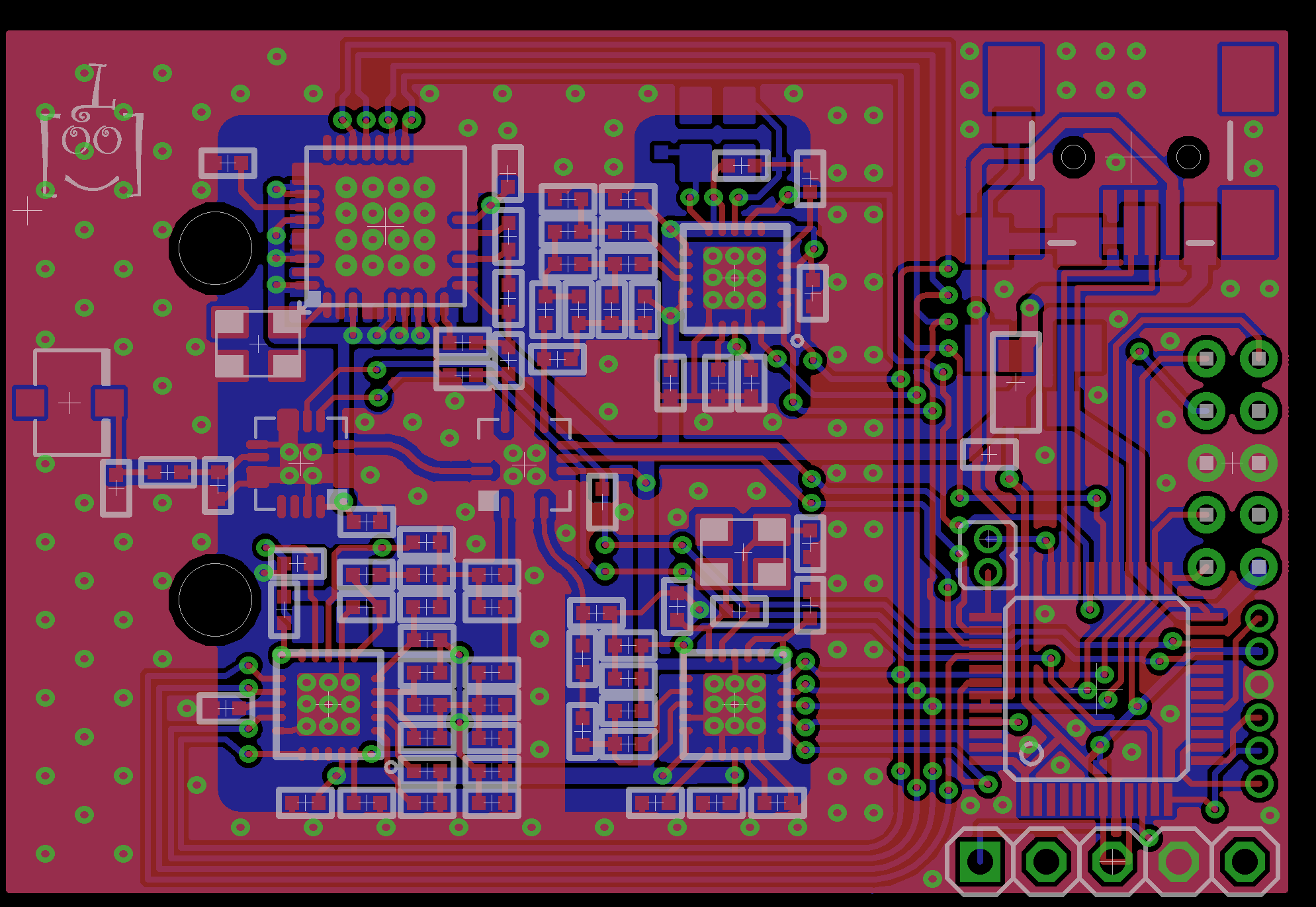
All flipped nearly as it was'ish.....need rest
- PhracturedBlue
-
- Offline
Less
More
- Posts: 4403
27 May 2014 15:36 - 27 May 2014 15:38 #23687
by PhracturedBlue
Replied by PhracturedBlue on topic Single-Board Universal Module
Thanks SadSack.
Send me the lbr/sch when you get a chance please.
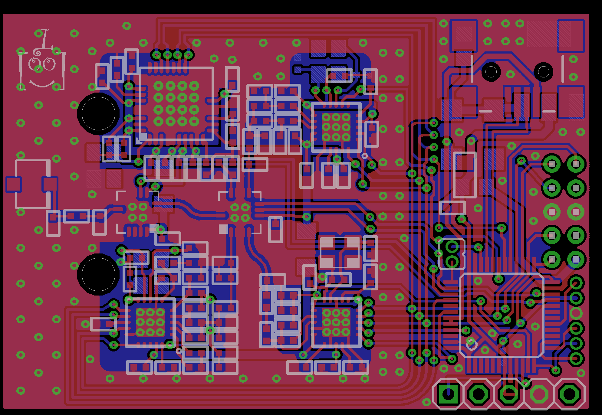
It looks really nice. You did a great job cleaning up the board.
Things still to do:
1) add a few more vias to the ground plane especially near the switch
2) remove all 90-degree corners (there are very few left, mostly on the bottom layer). These can radiate high-frequency noise and degrade performance
3) Add some more decoupling cap for the STM32F072
4) See if we can fit 1 or 2 10uF decoupling caps on Vcc in the RF section to help with power-supply stability given the long snaking nature of the route
Edit:
5) Add some mounting holes on the corners (left side). The existing holes are just to accept the pins on the Devo module, and won't be used for securing the part, since they'll be covered by the tin shield.
Send me the lbr/sch when you get a chance please.
It looks really nice. You did a great job cleaning up the board.
Things still to do:
1) add a few more vias to the ground plane especially near the switch
2) remove all 90-degree corners (there are very few left, mostly on the bottom layer). These can radiate high-frequency noise and degrade performance
3) Add some more decoupling cap for the STM32F072
4) See if we can fit 1 or 2 10uF decoupling caps on Vcc in the RF section to help with power-supply stability given the long snaking nature of the route
Edit:
5) Add some mounting holes on the corners (left side). The existing holes are just to accept the pins on the Devo module, and won't be used for securing the part, since they'll be covered by the tin shield.
Last edit: 27 May 2014 15:38 by PhracturedBlue.
- PhracturedBlue
-
- Offline
Less
More
- Posts: 4403
27 May 2014 15:50 #23688
by PhracturedBlue
Replied by PhracturedBlue on topic Single-Board Universal Module
As for BK2423 vs NRF24L01+, 5dBm Rx sensitivity is nothing to sneeze at (though I don't think we currently have any protocols that require Rx after binding?)
The BK2423 also has up to +3dBm output (vs 0dBm on the nrf24l01p), but this doesn't really help us much given we have a 25dBm amp with a max output of ~22dBm.
On the downside the BK2423 requires about 80% more current at equivalent power settings for Tx/Rx
The BK2423 also has up to +3dBm output (vs 0dBm on the nrf24l01p), but this doesn't really help us much given we have a 25dBm amp with a max output of ~22dBm.
On the downside the BK2423 requires about 80% more current at equivalent power settings for Tx/Rx
- SadSack
-
- Offline
Less
More
- Posts: 317
27 May 2014 16:04 - 27 May 2014 16:05 #23690
by SadSack
Replied by SadSack on topic Single-Board Universal Module
I can add more of a curve if you want more, not sure how much ?
Just edited curve near CY rf
Just edited curve near CY rf
Last edit: 27 May 2014 16:05 by SadSack.
- victzh
-
- Offline
Less
More
- Posts: 1386
27 May 2014 16:06 #23691
by victzh
Replied by victzh on topic Single-Board Universal Module
BK2423 is a clone, probably enhanced in the radio part (that's the datasheet, I would not believe blindly, Nordic can be conservative and Beken - optimistic), but lacking MCU to initialize the registers. The description of the registers specific to Beken (Register Bank 1) is very sparse and inaccurate with no single authoritative source. This lacking in the documentation is the main detractor for using Beken in my opinion.
Some protocols rely on auto-acknowledgement, which is equivalent to receiving.
How different is the layout?
Some protocols rely on auto-acknowledgement, which is equivalent to receiving.
How different is the layout?
- PhracturedBlue
-
- Offline
Less
More
- Posts: 4403
27 May 2014 16:18 #23692
by PhracturedBlue
Replied by PhracturedBlue on topic Single-Board Universal Module
The layout is the same except:
1) need to remove the solder resist over the pad
2) need to alter the passive component values
In theory (1) doesn't actually need to be different (we could solder the nrf24L01+ too, since apparently everyone does that anyway)
(2) is only an assembly/BOM issue
I'm surprised any protocol uses auto-ack during normal operation. given that the PA is only on the Tx, and the LNA cannot compensate for not having a PA on the Rx, you effectively have more range in Tx than in Rx. But I guess on a micro, noone cares. But for that case, we likely won't notice the difference anyway.
- PhracturedBlue
-
- Offline
Less
More
- Posts: 4403
27 May 2014 16:26 #23693
by PhracturedBlue
Replied by PhracturedBlue on topic Single-Board Universal Module
SadSack,
The ideal radius of a bend is > 3x the line width for all signal wires The smooth-curves are preferable to 45-degree angles where possible
The ideal radius of a bend is > 3x the line width for all signal wires The smooth-curves are preferable to 45-degree angles where possible
- SadSack
-
- Offline
Less
More
- Posts: 317
27 May 2014 16:40 #23694
by SadSack
Replied by SadSack on topic Single-Board Universal Module
Ok thanks. Have more time later.
Time to create page: 0.505 seconds
-
Home

-
Forum
-
Development
-
Development
- Single-Board Universal Module