- Posts: 4403
Single-Board Universal Module
- PhracturedBlue
-
Topic Author
- Offline
1) The table gets in the way of my scope lamp. I have a pen-lamp on the table which helps but could really be brighter
2) The bearings aren't working well. I have linear bearings and roller bearings. The linear bearings allow for smooth up/down motion, but do not allow the pen to turn. The roller bearings allow for smooth rotation, but don't provide smooth up/down motion
3) I need better software for the camera on the table. I can' get a full-screen image. Also, the camera is at too great of an angle, which is making perspective hard to see.
4) my pcbgrip actually works really well with this to hold the board, but I need to figure out a better way to secure it to the table (I need to take it off the stand to use it with the x/y, and things move around a little/getin the way.
I had to fix several tombstoned parts on this round, but otherwise things look ok. I haven't yet tested the board though. I'll work on that today.
Please Log in or Create an account to join the conversation.
- RoGuE_StreaK
-
- Offline
- Posts: 486
Please Log in or Create an account to join the conversation.
- PhracturedBlue
-
Topic Author
- Offline
- Posts: 4403
Please Log in or Create an account to join the conversation.
- PhracturedBlue
-
Topic Author
- Offline
- Posts: 4403
I have found 2 minor issues:
1) the holes for the usb plug are too small now that they've got vias in them. I had to cut the alignment holes off my USB plug.
2) there is too much paste on the regulator. That is actually just a problem with the stencil, so easily resolved.
Other than that, the new regulator and p-fet setup is working really well. A lot more reliable than the resistor setup I had previously.
The board boots up and communicates, but I haven't gotten all 4 modules working yet. I also have several software related issues I need to resolve before I can make any progress.
Please Log in or Create an account to join the conversation.
- mwm
-
- Offline
I'm curious as to why you think you could sell 100 of them. Based on the poor showing of the t-shirts, that seems optimistic. Sure, the module is actually useful, but better than an order of magnitude more?
Do not ask me questions via PM. Ask in the forums, where I'll answer if I can.
My remotely piloted vehicle ("drone") is a yacht.
Please Log in or Create an account to join the conversation.
- SadSack
-
- Offline
- Posts: 317
All active developers<<<as if you could keep them away
Devo10/8/12 Plug&Play<<<<no soldering, all using same hardware! Software only issues
Tranis <<< it's fits and does everything! Maybe controlled by tx?
Erx9 <<< as above
And all other brand, 3 wires + Antenna and bluetooth.
Is hundred gonna be enough
Ps Mwm post a survey in your blog on Regroup. Using your blog will hit vast majority of Regroup user.
Please Log in or Create an account to join the conversation.
- mwm
-
- Offline
Fewer than 10.SadSack wrote: Think of the long list of end user....
All active developers<<<as if you could keep them away
Don't forget us 6 owners! That's plug and play as well. I once swapped the CYRF between my 10 and 6 while chasing a problem. And the 7E users who would be willing to rig up the wiring for it. Now discount anyone who has a working MM, or has no interest in flying things that need a new module, and whose motto isn't "If it ain't broke, mod it!"SadSack wrote: Devo10/8/12 Plug&Play<<<<no soldering, all using same hardware! Software only issues
I think this is the real difference, as they wouldn't be ordering deviation T-shirts. I suspect they outnumber the first two groups by a fair factor, even after you discount the ones who've already built a module using the modified MM plans. I think that changes the shortage on T-shirt orders from a factor of 10 to more like a factor of 2 or 3, which I'm willing to believe.SadSack wrote: Tranis <<< it's fits and does everything! Maybe controlled by tx?
Erx9 <<< as above
Do not ask me questions via PM. Ask in the forums, where I'll answer if I can.
My remotely piloted vehicle ("drone") is a yacht.
Please Log in or Create an account to join the conversation.
- mikemacwillie
-
- Offline
- Posts: 152
Please Log in or Create an account to join the conversation.
- RoGuE_StreaK
-
- Offline
- Posts: 486
Did I have a mental lapse and just recommend a service that I probably first found out about in this thread?PhracturedBlue wrote: Yes I've talked with them.
Please Log in or Create an account to join the conversation.
- Richard96816
-
- Offline
- Posts: 208
I've got a smattering of experience in a large collection of pursuits, expert in none. Much to assimilate here. Pardon me if I mis-comprehend.
Using a multiplexer between the transceivers and antenna doesn't feel right. I've seen better solutions in the distant past, but sadly can't recall them in detail. The single package of the multiplexer is handy, but costly of performance, I think. Especially if only one transceiver is meant to be enabled at a time.
Also, adding a microprocessor to a project is a game changer. Wonderful in many ways, though not so in others. Designers often overlook the power of the processor and create potential harmful error conditions. The processor should not be able to bring harm to itself, surrounding circuitry or others through bad programming or random crash conditions. These possibilities should be surveyed at various stages of design and prototyping. Scrutinize all inputs and outputs and consider worst-case scenarios.
Allowing a processor to selectively enable and disable a bank of transceivers is handy and powerful. Allowing it to enable all simultaneously, if that is not intended, is probably a bad idea. It's easy enough to provide additional circuitry to prevent it. If you only intend to build one unit such may be excusable. Probably not if you're planning to build dozens.
Microprocessor design requires additional responsibility.
I was given a DAK bread machine as a gift, years ago. It would mix, knead, and cook loaves of bread from start to finish. Come back when it's done. Mine was the first version. Happened by the kitchen in the middle of the baking phase one time -- the whole unit was glowing bright red. Plastic parts were sagging. The heater was on runaway. The processor had crashed, perhaps due to heat. And it was in sole control of the heating element. Needless to say, the next version built in a discrete safety override. Certainly not of the same scale and impact as an r/c transmitter, but an important lesson many should learn.
Please be careful.
Please Log in or Create an account to join the conversation.
- frogamic
-
- Offline
- Posts: 5
I wonder if a similar sp4t rf switching circuit could be used with the multi-module to share a single antenna between the modules, or does it only work at unamplified power levels? (I know nothing about RF having chosen the computer science path over electrical engineering)
Please Log in or Create an account to join the conversation.
- Richard96816
-
- Offline
- Posts: 208
frogamic wrote: With this so operational already I'm hesitant to go putting holes in my new 7e for extra antennae when it might not be required soon.
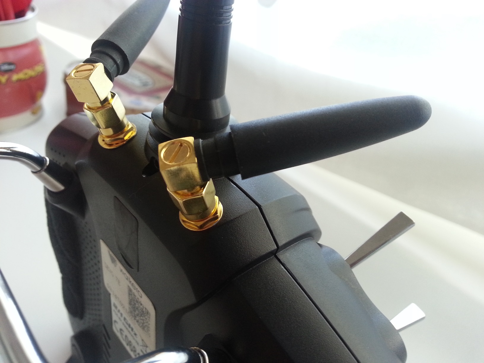
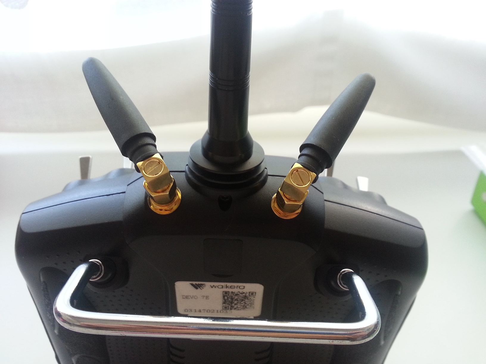
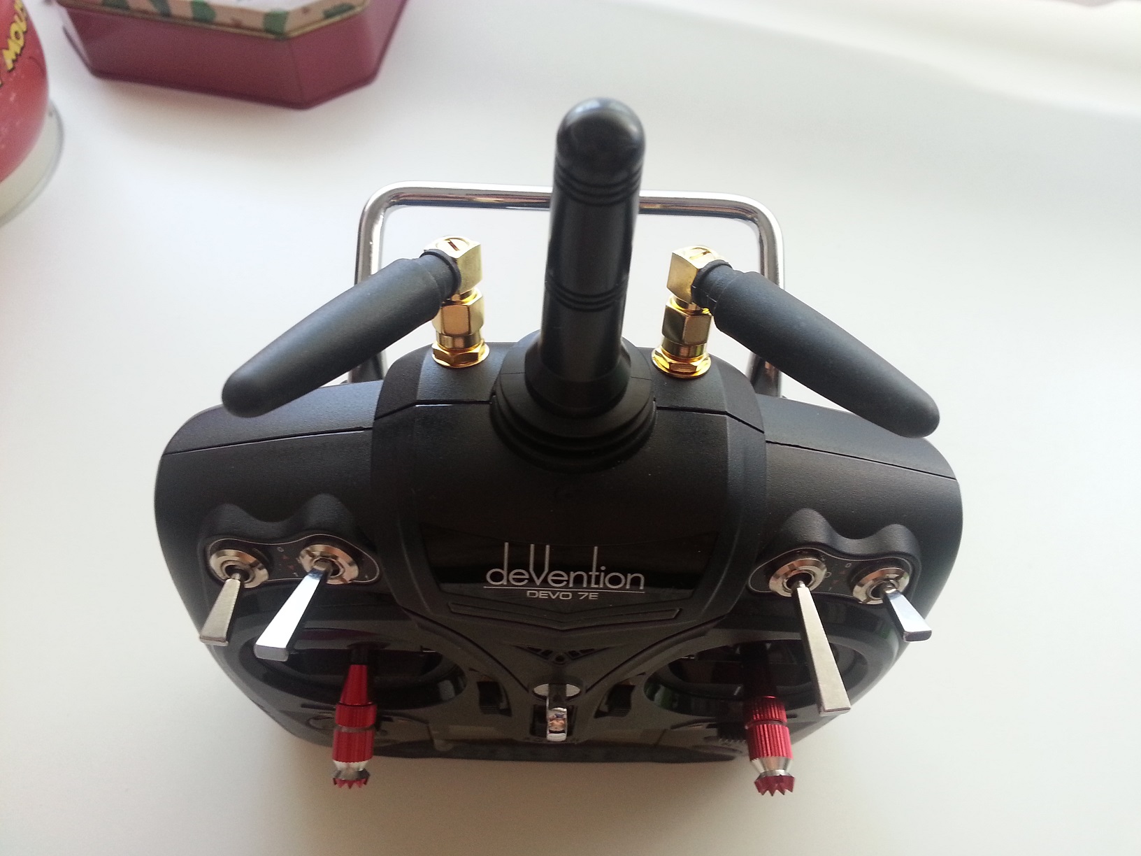
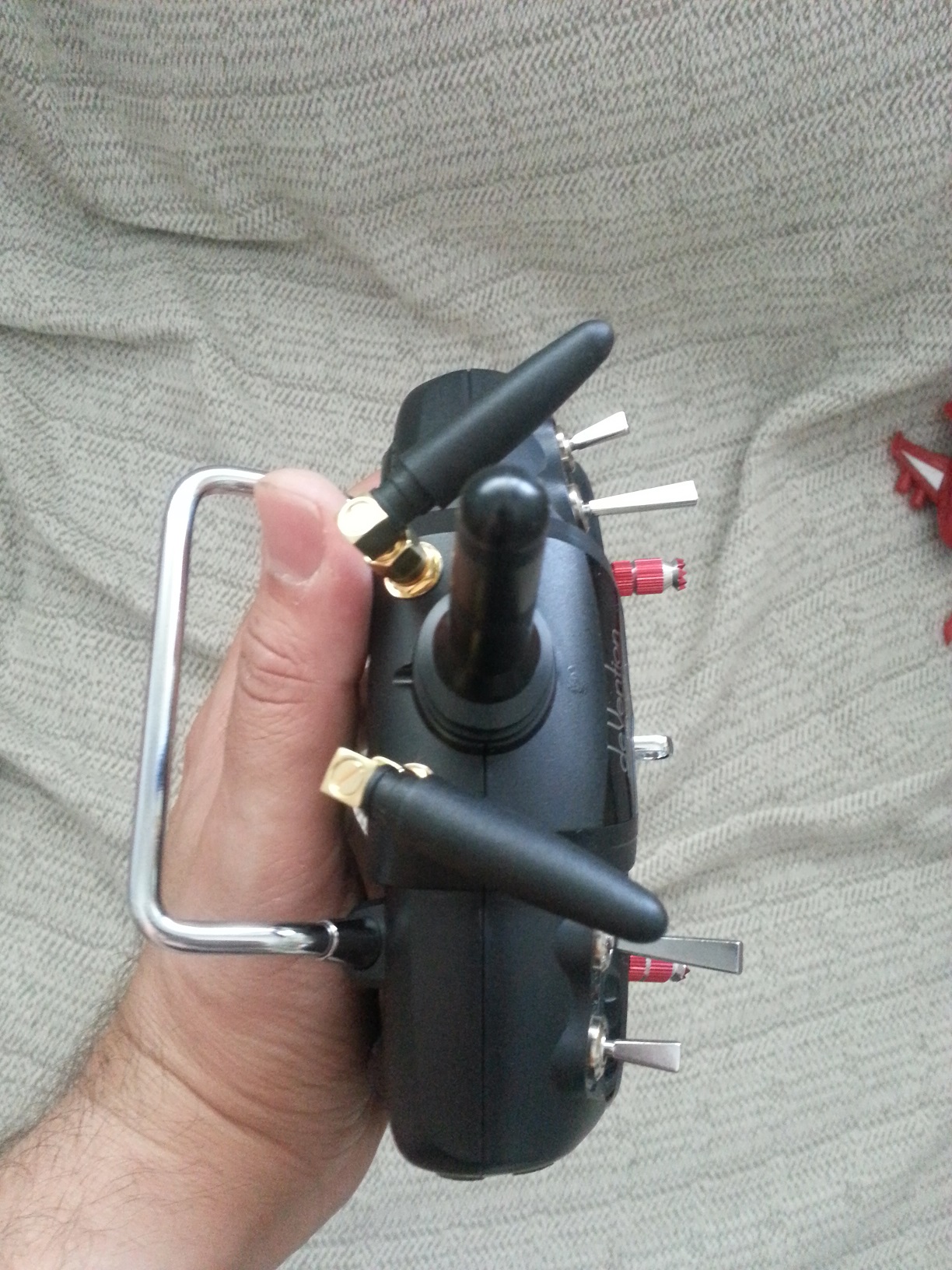
Putting an antenna farm atop your 7e is not necessary. These antennas are thin pieces of flexible wire within a plastic tube. The original 7e antenna housing will accommodate multiple such wires. Add a module, along with it's antenna and do a range test. I think you'll find things work just fine with a single tube housing multiple antenna wires. Especially since only one is energized at a time.
I've only added one module (nrf24l01) to my 7e so far. But it works great with two antennas in the tube. Range test your's and decide.
7e's with multiple antennas on top are pretty ugly.
Please Log in or Create an account to join the conversation.
- frogamic
-
- Offline
- Posts: 5
Richard96816 wrote: The original 7e antenna housing will accommodate multiple such wires. Add a module, along with it's antenna and do a range test. I think you'll find things work just fine with a single tube housing multiple antenna wires. Especially since only one is energized at a time.
I already replaced the stock antenna with a flexible one. I also don't like the multiple antenna look which is why I'd like to make a multiplexer. Based on the datasheet of the PE42641 it can handle 35dB of power, more than the modules put out. I'm sure I can handle the logic portions of the circuit but knowing nothing about RF I wouldn't know how to design that portion or if it's even viable.
Please Log in or Create an account to join the conversation.
- robca
-
- Offline
- Posts: 174
Keep in ind that having multiple antennas of the same frequency close and parallel to each other is not an ideal configuration: the unused antenna actually absorbs energy from the radiating one and weakens the signalRichard96816 wrote:
frogamic wrote: With this so operational already I'm hesitant to go putting holes in my new 7e for extra antennae when it might not be required soon.
Putting an antenna farm atop your 7e is not necessary. These antennas are thin pieces of flexible wire within a plastic tube. The original 7e antenna housing will accommodate multiple such wires. Add a module, along with it's antenna and do a range test. I think you'll find things work just fine with a single tube housing multiple antenna wires. Especially since only one is energized at a time.
I've only added one module (nrf24l01) to my 7e so far. But it works great with two antennas in the tube. Range test your's and decide.
7e's with multiple antennas on top are pretty ugly.
On the Devo 7e, it's far better to have one antenna in the tube, and the other 90 degrees, at the base of the tube. that way the antenna influence each other much less. In general, it's better not to have the antenna in the vertical tube, btw, since that tends to be pointed towards the model: that type of antenna has a radiating patter that is the weakest along the axis, so when you point the tip of the antenna towards the model, you have the weakest signal possible. Multiple antennas in the same vertical tube is the worse configuration possible, from a signal strength point of view. Antennas inside the body, as far from wires/metal as possible, parallel to the top of the radio is a better antenna configuration
Please Log in or Create an account to join the conversation.
- Richard96816
-
- Offline
- Posts: 208
robca wrote: Multiple antennas in the same vertical tube is the worse configuration possible, from a signal strength point of view.
My (limited) testing simply doesn't support that claim.
It's fairly easy to test, before you unnecessarily 'uglify' your radio.
Adding a larger, longer, flexible antenna housing does make sense. So use one that will hold multiple wires.
Please Log in or Create an account to join the conversation.
- moss
-
- Offline
- Posts: 40
A few wave-lengths apart should be safe, unless you need very long distance coverage. Placing the antennae inside the box should be OK unless it is absorptive plastic, which some black plastics, or metallized cases may be.
You don't need a Sigmund Freud sticking up out of the case, 2.4GHz 1/2 wave will fit easily inside the case.
Please Log in or Create an account to join the conversation.
- Durete
-
- Offline
- Posts: 610
I have installed both at my 7e with very good range.
www.ebay.com/itm/221597888621?_trksid=p2...e=STRK%3AMEBIDX%3AIT
Please Log in or Create an account to join the conversation.
- mikemacwillie
-
- Offline
- Posts: 152
Please Log in or Create an account to join the conversation.
- TilmanBaumann
-
- Offline
- Posts: 5
I actually just started investigating on how to use the Deviation firmware in a module context. With all the different RF chips on one board.
It seemed very doable. But also a massive project.
Imagine my surprise when I realised what this universaltx directory meant.
You guys rock!
I would love to implement the opentx side of that if I get it to work. I love the idea of a universal TX module on my Taranis transmitter.
How is the current status of this then?
Board revision 0.9.4 oshpark.com/shared_projects/PNfiUaYx is the current one?
And the BOM on the first page of this thread is current too?
Any idea how much it will cost to buy the whole BOM in low quantities? Is it at this point advisable for me to just go-ahead and buy those parts and the board?
Or is there anyone gearing up to do a production run?
What is the license of the board files?
Does this board already fit the outline of a JR module case? Or would I need to change the board outline for that still?
And can someone explain to me how the serial protocol works? Obviosuly I would not run it in PPM mode.
I can not figure out what source file does the parsing of that.
PS: There are various ways to get except from FCC.
The easiest one is to sell from outside the US and let the customers sort out importation problems.
But also test and prototype equipment is excemt IIRC. Sell bare boards with no case. Sparkfun also does not do any FCC certification for their stuff.
www.sparkfun.com/tutorials/398
Please Log in or Create an account to join the conversation.
- mwm
-
- Offline
Most of PB's code is GPL'ed under V3, but I couldn't find the sources for the board design to verify that.
The parts of the sparkfun page that are relevant for this are the one about "small manufacturer of open source hardware". Even selling kits is unclear, and not clearly a major advantage over something else. If we could set up a list of parts on some site that would let you click "add to cart" and get everything except maybe the PCB, that would be great. The real issue is that the assembly for this is beyond most people who'd like to have one. They probably don't have the equipment, and buying it just to make the one module is a bit excessive.
I'd like to create a non-profit organization that could coordinate contacts between people willing to build them gratis and those wanting to use them, maybe keep a US stock of parts that need ordering from china, but haven't been able to find anyone else interested, so don't have enough people to set up a legal non-profit.
Do not ask me questions via PM. Ask in the forums, where I'll answer if I can.
My remotely piloted vehicle ("drone") is a yacht.
Please Log in or Create an account to join the conversation.
-
Home

-
Forum

-
Development

-
Development

- Single-Board Universal Module


