Harvesting Joyway A7105 modules
- mwm
-
Topic Author
- Offline
- The module is in a socket, so it comes out trivially
- It's a hobby-grade Tx module designed with an internal antenna.
I don't think it's up to the D03 version, but it's clearly a nice upgrade from the harvested modules, and I suspect better than many other options. It might make a really good choice if you don't want external antennas on your Tx.
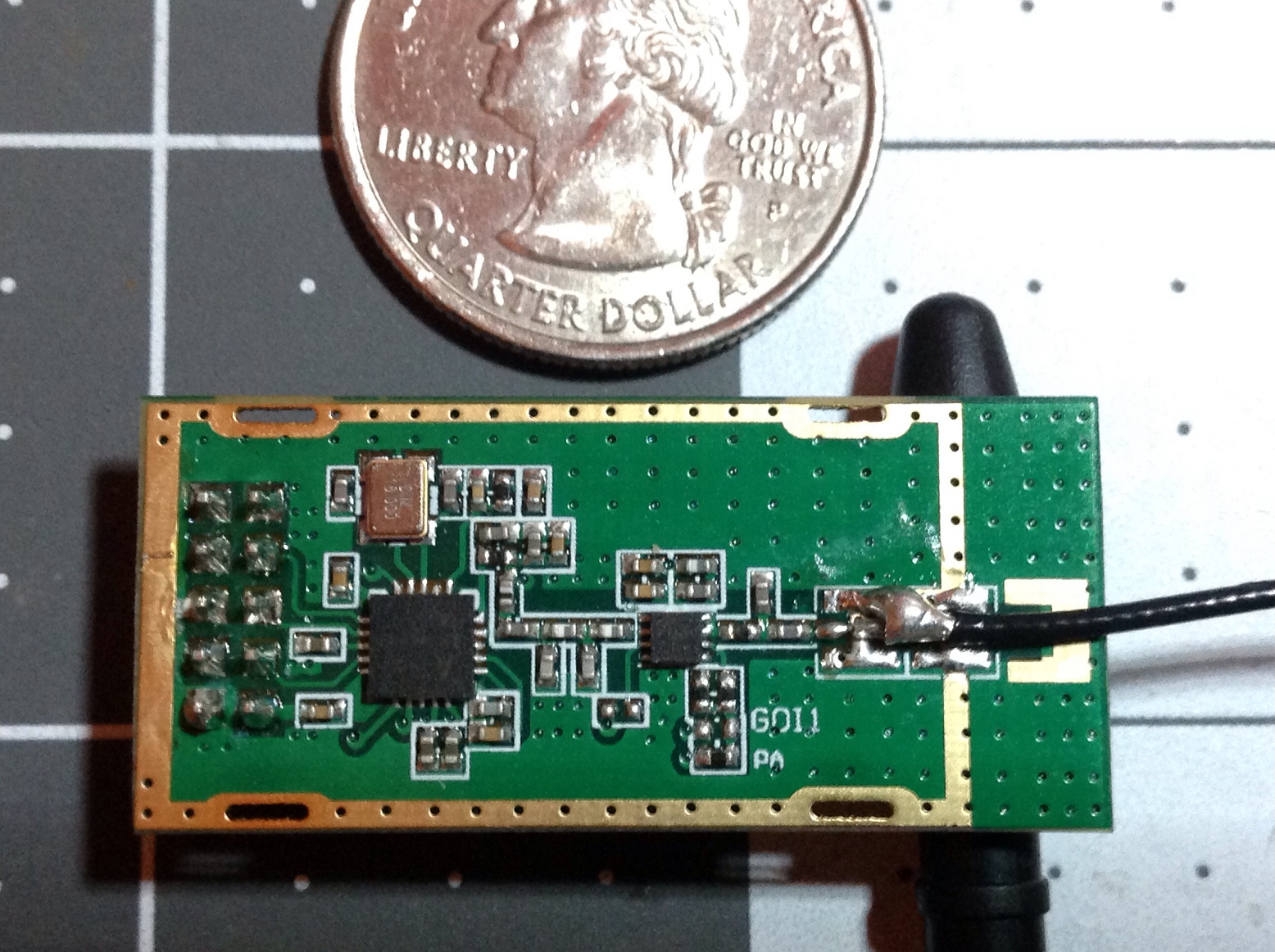
Here's a shot of the module with antenna attached: goo.gl/photos/JVLpyoCrorotUBPn7
I could use a bit of help with this, though. I've already got the data pins and ground from reverse engineering the Joysway protocol. But can anyone tell if this has a PA or similar on it?
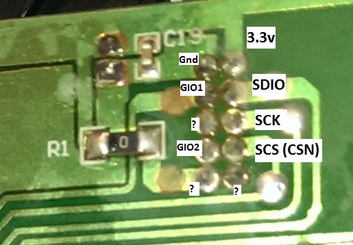
Here's a (bit blurry) shot of the top of the A7105 and pins used to reverse engineer the protocol: deviationtx.com/media/kunena/attachments/546/IMAG0181.jpg
And here's the back of the module from the same thread:
deviationtx.com/media/kunena/attachments/546/IMAG0184.jpg
If not, then I just need the five standard A7105 connections, right? If it has a PA, do I need jumpers on some of those pins, and if so where?
And while you're looking, can someone point out which pin gets 3.3Volts? I can probably find it myself, but figure it'll be faster for someone who knows what they're doing.
Do not ask me questions via PM. Ask in the forums, where I'll answer if I can.
My remotely piloted vehicle ("drone") is a yacht.
Please Log in or Create an account to join the conversation.
- Moeder
-
- Offline
- Posts: 796
Please Log in or Create an account to join the conversation.
- mwm
-
Topic Author
- Offline
Moeder wrote: From your blurry picture I'm pretty sure the IC marked "1110" and a lot code refers to a +23 dBm PA IC "AP1110". Also not the "PA" printed on the PCB close to it.
That would make it a really good module to harvest.
Do not ask me questions via PM. Ask in the forums, where I'll answer if I can.
My remotely piloted vehicle ("drone") is a yacht.
Please Log in or Create an account to join the conversation.
- hexfet
-
- Away
- Posts: 1955
Please Log in or Create an account to join the conversation.
- mwm
-
Topic Author
- Offline
Do not ask me questions via PM. Ask in the forums, where I'll answer if I can.
My remotely piloted vehicle ("drone") is a yacht.
Please Log in or Create an account to join the conversation.
- mwm
-
Topic Author
- Offline
Do not ask me questions via PM. Ask in the forums, where I'll answer if I can.
My remotely piloted vehicle ("drone") is a yacht.
Please Log in or Create an account to join the conversation.
- Deal57
-
- Offline
- Posts: 857
Deviation Devo7e 3way switch mod, A7105, NRF24L01
Devo6s 2x2 switch mod, trim mod, haptic, multimodule, A7105, NRF24L01, CC2500
Devo12e 4-in-1 with voice mod -- it speaks!!
Please Log in or Create an account to join the conversation.
- Deal57
-
- Offline
- Posts: 857
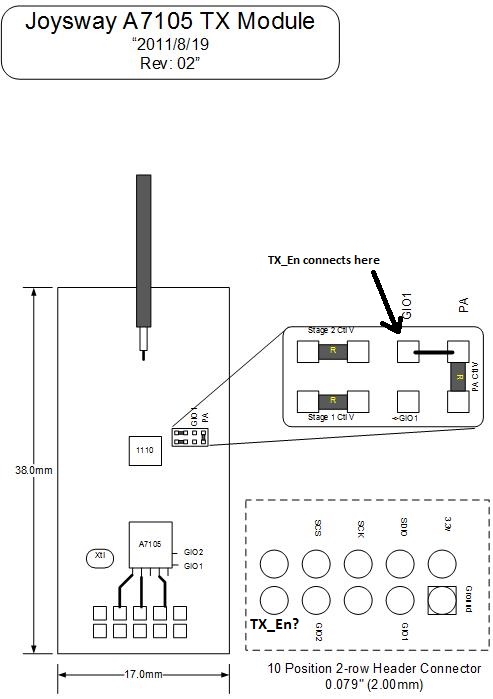
The GIO1 line appears to terminate at a jumper pad in the box in the upper right corner. It has a label GOI1 and PA, but the pads at GOI1 are not jumped. The side not connected goes into the PA voltage control circuits as described in the AP1110 documents . It appears to me that there is a circuit to control the PA.
The GIO1 and GIO2 pins are exposed at the 10-pin connector, along with SCS, SCK and SDIO and of course 3.3v and ground. There are three additional pins I cannot identify, marked with a "?" on this close-up. Does it make sense that they may include TX En or RX En? If they were those pins, where would they connect on the A7105 or support circuits? I ask because I don't want to pull the cover off my XL7105-D03 to see if I can match up traces.
My next step is to connect it to my transmitter and logic analyzer. I'll post my findings!
Deviation Devo7e 3way switch mod, A7105, NRF24L01
Devo6s 2x2 switch mod, trim mod, haptic, multimodule, A7105, NRF24L01, CC2500
Devo12e 4-in-1 with voice mod -- it speaks!!
Please Log in or Create an account to join the conversation.
- mwm
-
Topic Author
- Offline
Do not ask me questions via PM. Ask in the forums, where I'll answer if I can.
My remotely piloted vehicle ("drone") is a yacht.
Please Log in or Create an account to join the conversation.
- Deal57
-
- Offline
- Posts: 857
This pin would connect to the lower left corner position on the main board, and there is a lead on the main board (can't tell what it does; there's a resistor there). The pin connects to the un-jumped GIO1 pin in the jumper pad that attaches to the PA. IIUC, (on the XL7105D03) when GIO1 goes ON it energizes the PA for transmit, then when GIO1 goes OFF, GIO2 goes on and sets up for receive. If I'm getting this right, the transmitter MCU has control over GIO1 and TX_En like it works in the nighlies.
If that's the case, then i need to find RX_enable, and it's one of two pins. Is there a chance you could get a close up of the other side of the main transmitter board in the area of that 10-pin connector?
Can someone tell me if the process would work with just enabling/disabling GIO1?
Deviation Devo7e 3way switch mod, A7105, NRF24L01
Devo6s 2x2 switch mod, trim mod, haptic, multimodule, A7105, NRF24L01, CC2500
Devo12e 4-in-1 with voice mod -- it speaks!!
Please Log in or Create an account to join the conversation.
- mwm
-
Topic Author
- Offline
If not, I'll have to disassemble a radio to do this.
Do not ask me questions via PM. Ask in the forums, where I'll answer if I can.
My remotely piloted vehicle ("drone") is a yacht.
Please Log in or Create an account to join the conversation.
- Deal57
-
- Offline
- Posts: 857
And if you do happen to have a TX open, a photo would be helpful, but not needed right now.
Deviation Devo7e 3way switch mod, A7105, NRF24L01
Devo6s 2x2 switch mod, trim mod, haptic, multimodule, A7105, NRF24L01, CC2500
Devo12e 4-in-1 with voice mod -- it speaks!!
Please Log in or Create an account to join the conversation.
- Deal57
-
- Offline
- Posts: 857
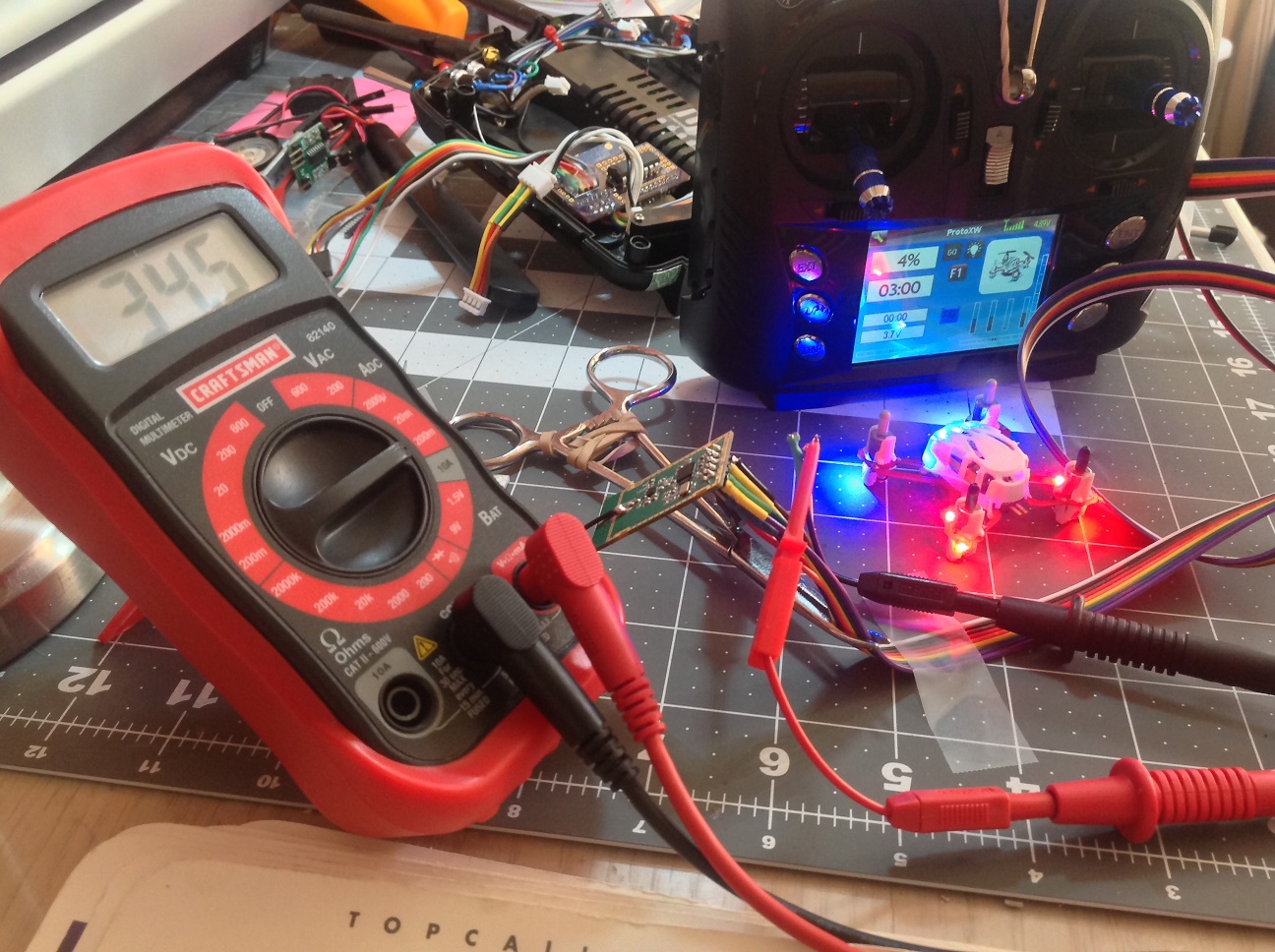
The cabling is pretty straightforward and matches up to my drawing from a few posts back. I still don't know if there is a pin for RX_EN, however power settings and telemetry are functional.
I measured the 3.3v power and got somewhat useful results on my cheap multimeter. It's pretty clear the TX power is responding to the model settings. At 100uw the board consumes about 24ma, at 30mw, between 32.5-35.5ma, at 100mw 36-37ma. I tried 150mw several times, and got varying results, a high of 38.5ma, a low of 36.7ma. The Hubsan was bound in all of these measurements with very low rpm on the motors. When I select a different protocol using the CYRF module, the power reads 25ma.
The range test worked well... I walked about 30ft in the house into another room and signal appeared to be stable, and telemetry showed the battery voltage correctly. During my power tests on the bench however, telemetry occasionally dropped out, so I'll have to keep track of it as I actually fly the little thing.
Now that it is installed, I will connect it to the logic analyzer and get a few captures.
Deviation Devo7e 3way switch mod, A7105, NRF24L01
Devo6s 2x2 switch mod, trim mod, haptic, multimodule, A7105, NRF24L01, CC2500
Devo12e 4-in-1 with voice mod -- it speaks!!
Please Log in or Create an account to join the conversation.
- Deal57
-
- Offline
- Posts: 857
Deviation Devo7e 3way switch mod, A7105, NRF24L01
Devo6s 2x2 switch mod, trim mod, haptic, multimodule, A7105, NRF24L01, CC2500
Devo12e 4-in-1 with voice mod -- it speaks!!
Please Log in or Create an account to join the conversation.
-
Home

-
Forum

-
Development

-
Development

- Harvesting Joyway A7105 modules


