- Posts: 402
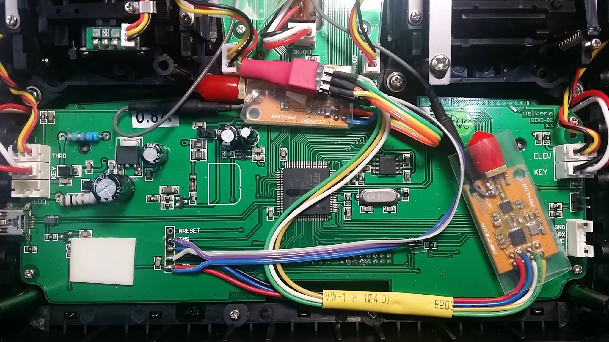
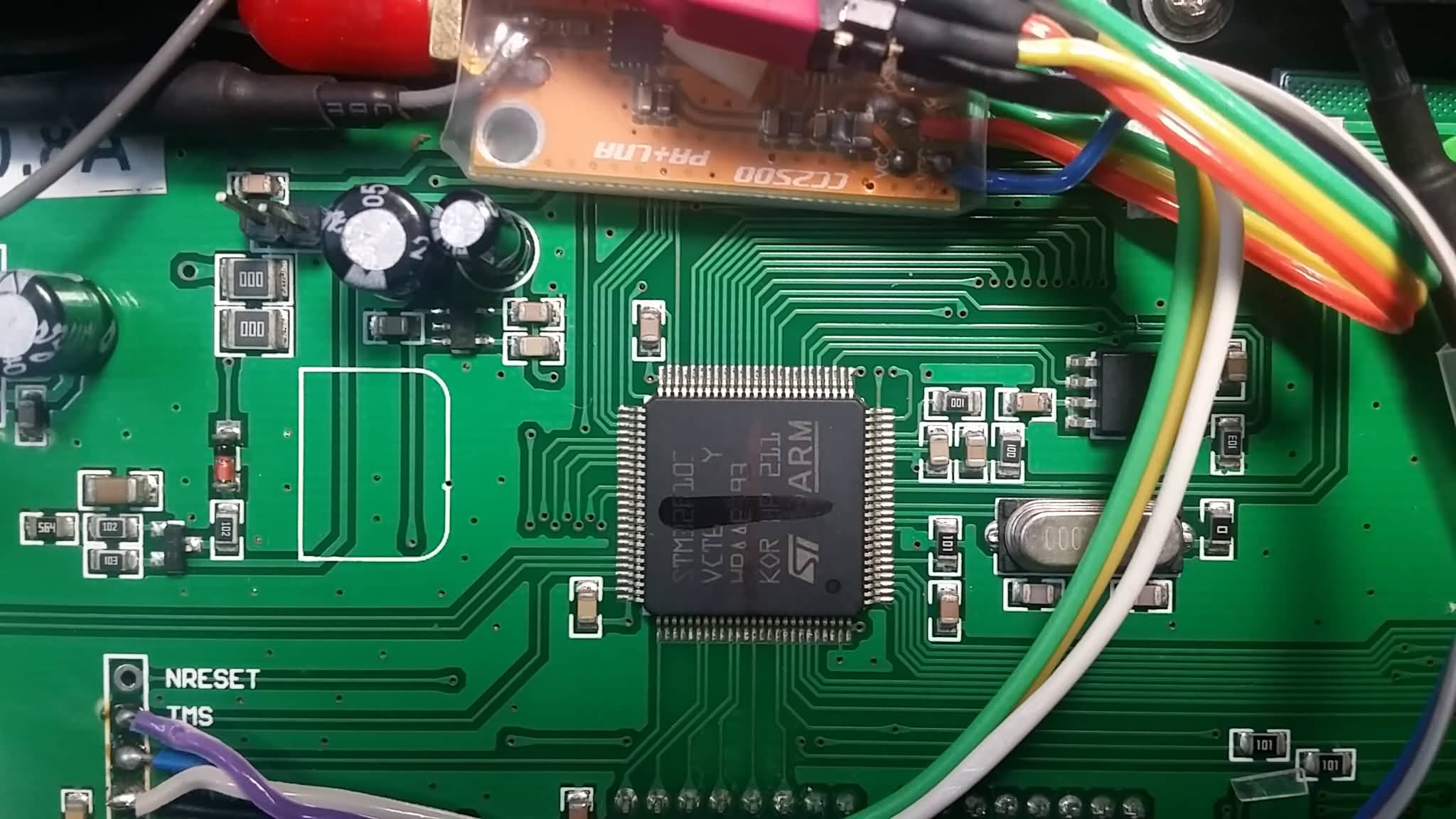
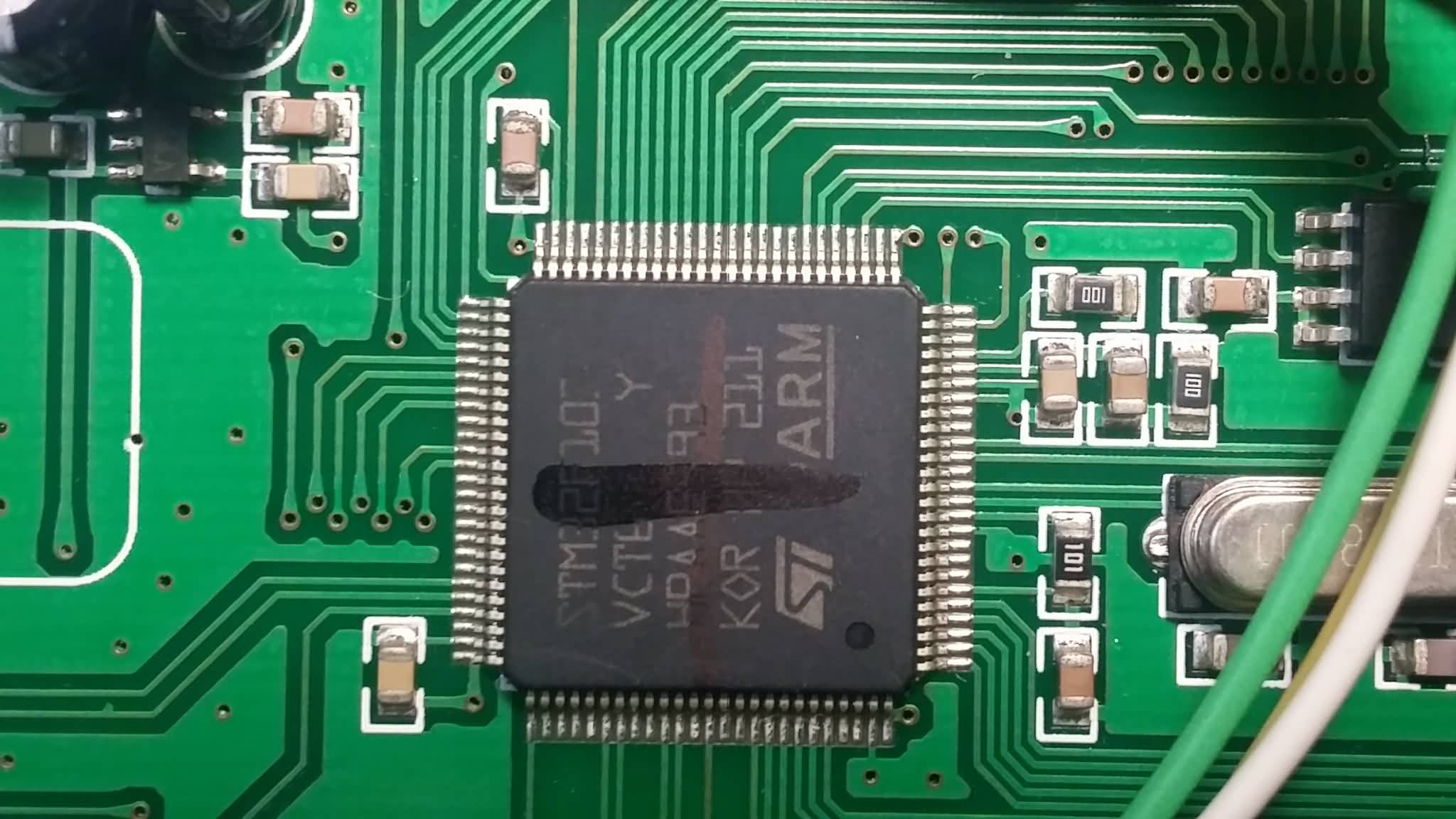
Devo 12s 3in1 / 4in1 RF module neat installation.
- blackmoon
-
- Offline
Mike this is a really neat idea!
mwm wrote: An interesting - an possibly easy, but beyond me - hack would be a board that mounts "over" the CPU chip, using POGO pins to connect to each of the unused pins on the MCU and providing a through hole or pin to connect things to on it. That way, you could add more RF modules to any of them, as well as switches and possibly even analog inputs (have to see if any of those pins are usable for analog input).
Once we confirm these things things work, we should add a page to the wiki docs on adding a third module to each of these. And possibly a new forum thread on the topic of adding a third module sans the MM. It's a pretty common request.
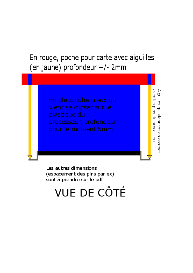
The pcb where the pogo pins should be located shouldn't be hard to do, 3d print a cap for it that would lock onto the ST chip is out of my league though.
I'll ask a friend that is good at designing stuff if he can do something for the MCU cap. I'll give him the Devo7E MCU datasheet, then if he comes with something I'll try the pcb (I already have an idea about it, i think it could work).
So those" A4 (20), A8 (41), A15 (50), B3 (55), B4 (56), B9 (62), and C12 (53). The GPIO's for C13, C14, C15" are the usable pins on the 7E.
D0 and D1 not so sure ?
Please Log in or Create an account to join the conversation.
- mwm
-
- Offline
blackmoon wrote: The GPIO's for C13, C14, C15" are the usable pins on the 7E.
D0 and D1 not so sure ?
Are you sure C13, C14 and C15 are usable? Those cpu pins are tied to the RTC and various oscillators as secondary functions. As are D0 and D1. I'd have to dig through the sources and see which clock/oscillators are used to figure out if they can be used.
Edit: Pins C13, C14 and C15 share the same functionality on the 8, and are used there. So those should indeed be ok. They are CPU pins 2, 3 and 4. Still not sure about D0 and D1, though, as those are oscillator in/out, and are given dedicated pins on the 8.
Do not ask me questions via PM. Ask in the forums, where I'll answer if I can.
My remotely piloted vehicle ("drone") is a yacht.
Please Log in or Create an account to join the conversation.
- mwm
-
- Offline
TomPeer wrote: what about the 8s, I don't use this tx as much as the 10, so i would like to try at the 8s first.
Unused pins are A4 (29), A8 (67), A15 (77), B3 (89), B4 (90), C5 (34), D2 (83), D3 (84), D6 (87), D12 (59), D13 (60), E0 (97), and E1 (98).
Those are all probably unused on the 6 as well, however with C9 and C10 (which connect to the two extra switches on the
Next step is the same as for the 7E: check the hardware to see if any of those pins have exposed pads.
Do not ask me questions via PM. Ask in the forums, where I'll answer if I can.
My remotely piloted vehicle ("drone") is a yacht.
Please Log in or Create an account to join the conversation.
- blackmoon
-
- Offline
- Posts: 402
mwm wrote:
Are you sure C13, C14 and C15 are usable? Those cpu pins are tied to the RTC and various oscillators as secondary functions. As are D0 and D1. I'd have to dig through the sources and see which clock/oscillators are used to figure out if they can be used.
Edit: Pins C13, C14 and C15 share the same functionality on the 8, and are used there. So those should indeed be ok. They are CPU pins 2, 3 and 4. Still not sure about D0 and D1, though, as those are oscillator in/out, and are given dedicated pins on the 8.
Oops forgot the question mark, I was in fact asking you if those would be the ones usable.
If not to much hassle could you confirm without doubt which ones can be used ? So I can forward that to the 3D slave
Thank you.
Please Log in or Create an account to join the conversation.
- mwm
-
- Offline
blackmoon wrote: If not to much hassle could you confirm without doubt which ones can be used ? So I can forward that to the 3D slave
Thank you.
It's in the earlier message. For the 7e, definetely A4 through C12. For the 8, A4 through E1. I believe C12, 13 and 14 on the 7e should also be free since they are used on the 8 for switches and the like and have the same functionality on both mcus.
Do not ask me questions via PM. Ask in the forums, where I'll answer if I can.
My remotely piloted vehicle ("drone") is a yacht.
Please Log in or Create an account to join the conversation.
- Fernandez
-
- Offline
- Posts: 983
PA0 and PA4 are certainly unused, but no exposed pins. Phracured blue have connected analog pots to those.
Please Log in or Create an account to join the conversation.
- mwm
-
- Offline
And again, that PB failed to find pads isn't a good sign for there being pads.
Do not ask me questions via PM. Ask in the forums, where I'll answer if I can.
My remotely piloted vehicle ("drone") is a yacht.
Please Log in or Create an account to join the conversation.
- TomPeer
-
- Offline
- Posts: 303
mwm wrote:
TomPeer wrote: what about the 8s, I don't use this tx as much as the 10, so i would like to try at the 8s first.
Unused pins are A4 (29), A8 (67), A15 (77), B3 (89), B4 (90), C5 (34), D2 (83), D3 (84), D6 (87), D12 (59), D13 (60), E0 (97), and E1 (98).
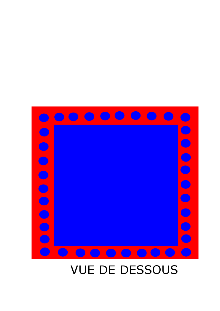
Thanks for this information but i do not know how to find those. i guess i just count the pins from a givven point? for example A4 is pin number 29? Where do i start to count?
Please Log in or Create an account to join the conversation.
- dc59
-
Topic Author
- Offline
- Posts: 799
Please Log in or Create an account to join the conversation.
- Deal57
-
- Offline
- Posts: 857
Since there are three package (64-pin for 7, 100 pin for 6 and 8 and 10, 144 for 12) we need three pogos! Well, that and consensus on which pin functions to use.
Deviation Devo7e 3way switch mod, A7105, NRF24L01
Devo6s 2x2 switch mod, trim mod, haptic, multimodule, A7105, NRF24L01, CC2500
Devo12e 4-in-1 with voice mod -- it speaks!!
Please Log in or Create an account to join the conversation.
- mwm
-
- Offline
Deal57 wrote: Added pin reference illustrations to the spreadsheet where I've consolidated all of PB's pin usage for all the processors (post 43357). There are a few unused pins from TX to TX, that are also available on similar builds (e.g. the F7 uses almost all the 7e pins and a few more, the 8s uses the same pins as the 6s, etc.). I've examined the 6s closely (and related 8s pics) and while there are pins available, none of them appear to be exposed on pads.
Just to clarify - no unused pins on the 8s with pads. The 6S has pads for controls on the 8s (two extra switches and two extra trims) that aren't connected to controls. The trims are part of the button matrix, and hence unusable for other things, the two switches are digital GPIO pins, and should be usable for anything that that needs.
Since there are three package (64-pin for 7, 100 pin for 6 and 8 and 10, 144 for 12) we need three pogos! Well, that and consensus on which pin functions to use.
Why not have the 3d CAD file have places for all the pins of interest, and then the end user can just install the ones they want? There will be a problem with strength, but we need prints to test with.
Do not ask me questions via PM. Ask in the forums, where I'll answer if I can.
My remotely piloted vehicle ("drone") is a yacht.
Please Log in or Create an account to join the conversation.
- blackmoon
-
- Offline
- Posts: 402
Please Log in or Create an account to join the conversation.
- mwm
-
- Offline
I just realized what's missing from this thread: links to the product pages! I went looking for them, but couldn't find all three. At least, I thought there were three: a 3-in-1 module, a 4-in-1 module, and a multimodule (with a rotary dial). Found the 3-in-1 and the multimodule, but not the 4-in-1.
Someone want to add them? Best if dc59 goes back and adds them to the first post.
Do not ask me questions via PM. Ask in the forums, where I'll answer if I can.
My remotely piloted vehicle ("drone") is a yacht.
Please Log in or Create an account to join the conversation.
- blackmoon
-
- Offline
- Posts: 402
world.taobao.com/item/526271178299.htm?f...a.7728556.0.0.nacaZN
Please Log in or Create an account to join the conversation.
- dc59
-
Topic Author
- Offline
- Posts: 799
I have added the product link to first post.
@blackmoon
Thanks!!
Please Log in or Create an account to join the conversation.
- TomPeer
-
- Offline
- Posts: 303
dc59 wrote:
TomPeer wrote: Does this mean you can solder in a third module (3 extra modules) without the multi module?
Yes, it is! use B7 pin to be third chip select.
I soldered in the cc2500 on pin B7, The tx recognizes the module and seems to work fine. Now i have to order some frsky receivers.
Thank you dc59!!
Please Log in or Create an account to join the conversation.
- FDR
-
- Offline
Which TX?TomPeer wrote: I soldered in the cc2500 on pin B7, The tx recognizes the module and seems to work fine. Now i have to order some frsky receivers.
Thank you dc59!!
Please Log in or Create an account to join the conversation.
- TomPeer
-
- Offline
- Posts: 303
I would like to do this also with a devo 8s but i do not know to witch pin i could use. i do not know witch is 1, 2 and so on.
Please Log in or Create an account to join the conversation.
- FDR
-
- Offline
Please Log in or Create an account to join the conversation.
- TomPeer
-
- Offline
- Posts: 303
I shall try to put a cc2500 module on one of the pins MWM provided.
I report back if succesfull (or not).
Please Log in or Create an account to join the conversation.
-
Home

-
Forum

-
Development

-
Development

- Devo 12s 3in1 / 4in1 RF module neat installation.

