- Posts: 50
New color skin
- henkerhaus
-
Topic Author
- Offline
Splash Screen
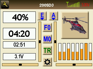
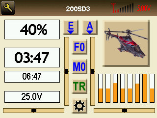
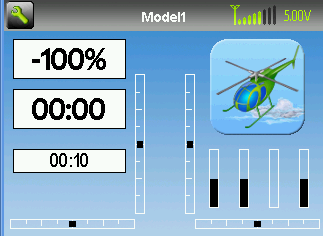
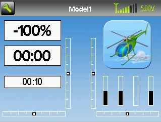
Main Page (Low Dual Rates, Flight mode, Mix Switch, Throttle Hold not Enabled, Gear Up)
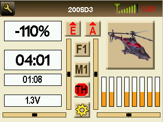
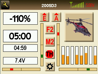
Main Page (High Dual Rates, Mid Flight mode/Mix Switch, Throttle Hold Enabled, Gear Down)
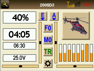
Main Page (Reduced Tx Powers are Amber)
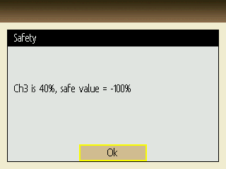
Main Page (Lowest 2 Tx Powers are Red) (I wished I could click in the Tx Power icon to go to the Model Menu to change the Tx Power. It would be a nice added feature.)
Main Page (Trim colors are green - Right / Down, Red - Left / Up)
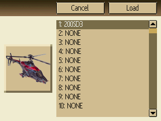
Load Model Page
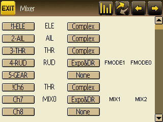
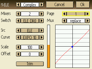
Mixer Page (Note Menu Button icons are provided in both Dark w/Amber Graphics and Amber w/ Dark Graphics. I couldn't decide which I liked better, so I just made both.)
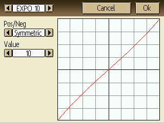
Mixer Editor and Curve Editor have white background plots, w/Red curve line on a gray grid)
The curve line is fairly thin at 1 pixel wide. It would be nice if the displayed curve could be set to say 1, 2, or 3 pixels thick (globally), for better visibility. It would also be nice if the curve point being edited was highlighted on the curve with a contrasting dot (like as shown on the screen above) Also, it might be nice if the number of gridlines changed to the number of points specified. (Just a thought)
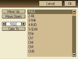
Re-Order Channels Page
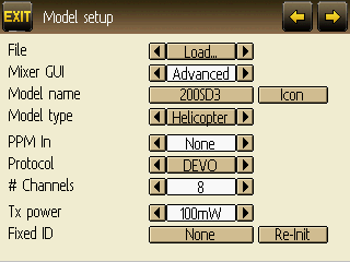
Model Setup Page
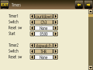
Timers Page
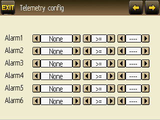
Telemtry Config Page
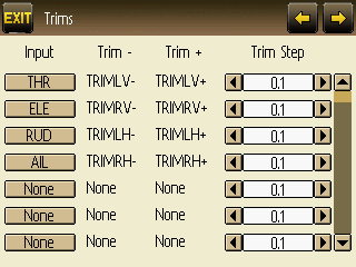
Trims Page
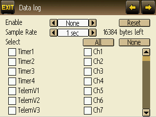
Data Log Page (Not addressed in user manual)
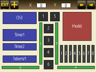
Main Page Config Page (This page doesn't appear to function the way the manual describes (The images shown on page 14 don't exist; It appears to be purely free format editable. (Which is nice))
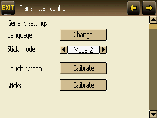
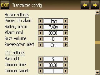
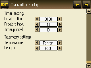
Tx Config Page
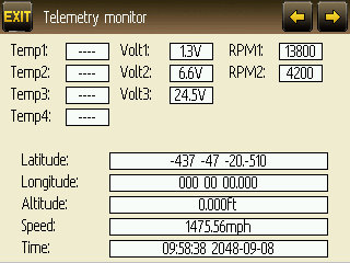
Telemetry Monitor Page
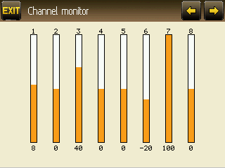
Channel Monitor Page
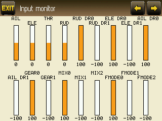
Input Monitor Page
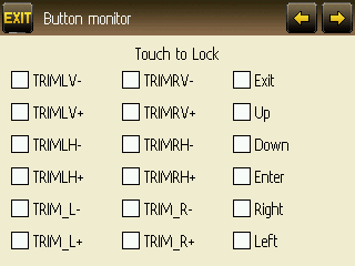
Button Monitor Page
Version Page (The url on this page need to be a dark color, but I couldn't find a place to set it in the .ini files.)
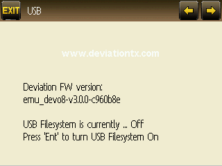
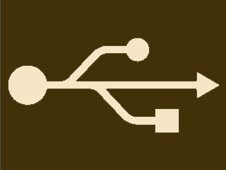
here is my revised USB screen (Dark Brown Background with a cream USB icon)
Here is the complete updated filesystem. Model1 is the only model file changed. Media folder contains duplicate menu buttons for reversed button colors if preferred. Enjoy.
Please Log in or Create an account to join the conversation.
- PhracturedBlue
-
- Offline
- Posts: 4403
Did you find anything you wanted to be able to customize (themewise) and couldn't?
I'll have to think about the graph-line thickness, I'm not sure how easily that can be done. But any colors you wanted to change that were fixed (besides the USB screen)?
Please Log in or Create an account to join the conversation.
- WheresWaldo
-
- Offline
- Posts: 253
Is there a way to tint the dialog box?
Please Log in or Create an account to join the conversation.
- rbe2012
-
- Offline
- So much to do, so little time...
- Posts: 1433
@PB: When I looked at henkerhaus' work I have seen that he has embossed his icon what looks better for me than a flat icon. This can be done with the icon, but could also done by the gui.
It might be an interesting feature to create an image used as a frame and place the icon (with transparency) on top. I think about an image which defines the corners and only a small part of the sides which is replicated as often as needed (to save space and to allow different icon sizes. This way we could easily change the frames for all icons at once.
Something like this (height=frame width, corners upper left, ur, ll, lr, border top, l, b, r):
Please Log in or Create an account to join the conversation.
- FDR
-
- Offline
If there is a frame it looks ugly when not aligned with the other controls, and it is difficult to always achieve perfect aligning...
EDIT: ...especially if there are different icon sizes...
Please Log in or Create an account to join the conversation.
- PhracturedBlue
-
- Offline
- Posts: 4403
For instance, maybe we could support a custom USB screen if the filesystem is present and the file exists...probably easy, and maybe give that little bit extra customization.
Please Log in or Create an account to join the conversation.
- henkerhaus
-
Topic Author
- Offline
- Posts: 50
Please Log in or Create an account to join the conversation.
- henkerhaus
-
Topic Author
- Offline
- Posts: 50
Please Log in or Create an account to join the conversation.
- henkerhaus
-
Topic Author
- Offline
- Posts: 50
Please Log in or Create an account to join the conversation.
- henkerhaus
-
Topic Author
- Offline
- Posts: 50
Please Log in or Create an account to join the conversation.
- PhracturedBlue
-
- Offline
- Posts: 4403
Centerlines are already in the code:henkerhaus wrote: The only other things that stood out for me was I would have liked to be able to specify the outline_color of the scrollbar fg_color as black for higher contrast of the position indicator. Similarily, I would have liked to be able to specify the outline_color of the trim fg_color_pos and fg_color_neg as black also for higher contrast of the position indicator. A centerline on the trim indicators in the outline_color would be nice too. As I mentioned earlier, the color of the URL reference on the Version screen needed to be black instead of white, but if that was Black by default, I wouldn't ever need to change it.
You also can create an outline for the trim position, though it requires a code change. the original code looked like this:
but I didn't find it had enough contrast when the bar was blue/red so I disabled that part, though the code is still present.
Please Log in or Create an account to join the conversation.
- henkerhaus
-
Topic Author
- Offline
- Posts: 50
Please Log in or Create an account to join the conversation.
- henkerhaus
-
Topic Author
- Offline
- Posts: 50
Please Log in or Create an account to join the conversation.
- henkerhaus
-
Topic Author
- Offline
- Posts: 50
Please Log in or Create an account to join the conversation.
- PhracturedBlue
-
- Offline
- Posts: 4403
No, you can't turn them on without building a new DFU. Maybe there's something I can do though. the reason the hash marks are on one side is that the bar is one pixel smaller, so you can (just) still see them when the position box overlaps. In practice I'm skeptical this is visiblee on the Tx.henkerhaus wrote: The bottom screen trims are exactly what I'd want, but I'd make the Outlines Black. Can i "turn these on" by adding some color definition lines to the config.ini file? Or does it require a different DFU binary? (Not to nit pick too much, but it would look better if the Left vertical trim outline was a mirror of the Right, instead of a duplicate. But I know, it's easier to program it as a duplicate. Perhaps if the short segments were all centered, then it wouldn't matter
They went through a few rounds of different implementations. I don't know if they tried drawing the hash marks after the cursor (in which case you could center them)
Please Log in or Create an account to join the conversation.
- rbe2012
-
- Offline
- So much to do, so little time...
- Posts: 1433
diff -r 40441afc2802 src/gui/320x240x16/_bargraph.c
--- a/src/gui/320x240x16/_bargraph.c	Mon Dec 02 20:04:21 2013 -0800
+++ b/src/gui/320x240x16/_bargraph.c	Tue Dec 03 16:45:59 2013 +0100
@@ -40,17 +40,17 @@
         LCD_FillRect(x, y, width, height, disp->bg_color);
     }

-    //Bar trim points
-    int hmap[] = {height / 2, 3 * height / 4, height / 2, height, height / 2, 3 * height / 4, height / 2};
-    for (int i = 0; i < 7; i++) {
-        LCD_DrawFastVLine(x + (i + 1) * width / 8, y, hmap[i], disp->outline_color);
-    }
     // Main rectangle
     if (TRIM_THICKNESS) {
         LCD_FillRect(xpos - (TRIM_THICKNESS / 2)-1,
                      y + TRIM_MARGIN,
                      TRIM_THICKNESS, height - TRIM_MARGIN * 2, color);
     }
+    //Bar trim points
+    int hmap[] = {height / 2, 3 * height / 4, height / 2, height, height / 2, 3 * height / 4, height / 2};
+    for (int i = 0; i < 7; i++) {
+        LCD_DrawFastVLine(x + (i + 1) * width / 8, y + (height - hmap[i]) / 2, hmap[i], disp->outline_color);
+    }
     // Marking rectangle
     if (TRIM_INNER_THICKNESS) {
         LCD_FillRect(xpos - (TRIM_INNER_THICKNESS / 2)-1,
@@ -69,17 +69,17 @@
         LCD_FillRect(x, y, width, height, disp->bg_color);
     }

-    //Bar trim points
-    int wmap[] = {width / 2, 3 * width / 4, width / 2, width, width / 2, 3 * width / 4, width / 2};
-    for (int i = 0; i < 7; i++) {
-        LCD_DrawFastHLine(x, y + (i + 1) * height / 8, wmap[i], disp->outline_color);
-    }
     // Main rectangle
     if (TRIM_THICKNESS) {
         LCD_FillRect(x + TRIM_MARGIN,
                      y + (height - val) - (TRIM_THICKNESS / 2) - 1,
                      width - TRIM_MARGIN * 2, TRIM_THICKNESS, color);
     }
+    //Bar trim points
+    int wmap[] = {width / 2, 3 * width / 4, width / 2, width, width / 2, 3 * width / 4, width / 2};
+    for (int i = 0; i < 7; i++) {
+        LCD_DrawFastHLine(x + (width - wmap[i]) / 2, y + (i + 1) * height / 8, wmap[i], disp->outline_color);
+    }
     // Marking rectangle
     if (TRIM_INNER_THICKNESS) {
LCD_FillRect(x + TRIM_MARGIN * 2,Please Log in or Create an account to join the conversation.
- PhracturedBlue
-
- Offline
- Posts: 4403
Please Log in or Create an account to join the conversation.
- henkerhaus
-
Topic Author
- Offline
- Posts: 50
With the trims centered, and the trim position indicator being black, the outline on the trim position indicator isn't useful, but my thought was that when the trim indicators ARE off center, and the colors are not black, a dark contrasting border color would improve visibility of the indicator edges.
One issue I have noticed about the trim position / indicator has to do with the trim step size. The manual indicates (and my observation is) that there are +/- 100 trim steps available, regardless of the trim step size specified. It seems to me that when the step size is changed, the position of the indicator should also move by that number of steps.
For example, if the step size is set to the 0.1 default, then I would have to press the trim button 100 times to reach the limit. if I changed the trim step to say 0.5, then I should only have to press the trim button 20 times to reach the limit, because the trim setting (and the indicator) should move in increments of 5 instead of 1.
My observation was that with the trim step set to 0.5, I still had to press the trim button 100 times to get to the limit. This would result in a trim change 5x greater than with the step size at 0.1.
Also, from a user stand point, I think the trim step would be clearer to understand if the user entered values ranged from 0 to 100, in increments of 1 (since there are +/- 100 steps), instead of 0 to 10 (?) in increments of 0.1. The 0.1 step size was a little confusing to me i.e. I wasn't sure if the range was 0 - 100, in increments of 0.1 (which would actually equal 1000 steps) or if it was 0 - 10 in increments of 0.1 = 100 steps. If the intent was 100 steps = 100% trime range, the I think it would be clearer to use trim step values in the interface of 0-100, in increments of 1.
Please Log in or Create an account to join the conversation.
- rbe2012
-
- Offline
- So much to do, so little time...
- Posts: 1433
The trim step defines indirectly the value which can maximally added. With a trim step of 0.1 and 100 steps you get +/-10%, with a step of 0.5 and 100 steps you get +/-50%. It is not wanted to fix the maximum addition to 10%.
Please Log in or Create an account to join the conversation.
- EduardS
-
- Offline
- Posts: 36
Please Log in or Create an account to join the conversation.
-
Home

-
Forum

-
Model Configs, Templates, Skins

-
Custom Skins

- New color skin

