
- Posts: 296
No RF power from 7e
- cmpang
-
Topic Author
- Offline
Less
More
06 Mar 2013 05:54 #7412
by cmpang
No RF power from 7e was created by cmpang
I flew and crashed my quad last Sunday. The bird was flying close enough that I can in no doubt that it was a radio signal problem.
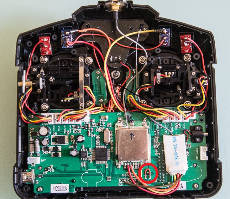
Went home and toke out my spectrum analyser can confirm there is no RF output from my 7e.
Tracing back and compared with my friend's healthy 7e revealed that the voltage at Pin6 of the RF module is only 2V instead of my friend's 4.8V.
My trusty multimeter points me to a SL (short link) that was open circuited. Shorting out the SL, burning in for one night and the transmitter is working ok..
A side issue that I cannot be 100% certain is that one day before the break down, I used the transmitter continously for 3 hours to run my R/C battle tank. So it comes to my thinking that may be after the diode mod, the RF power is raised and hence the drawing current also increases towards the limit of the SL can handle.
It is only a speculation, but I think it would be good to post it up here for those who get the same problem in the later times can make reference to..
BTW, there is absolutely no harm to short out the SL before hand just to play safe..
- Mullson
-
- Offline
Less
More
- Posts: 114
06 Mar 2013 10:32 #7424
by Mullson
Replied by Mullson on topic No RF power from 7e
What do you think the SL is there for in the first place? Maybe a stupid question.
With your antenna mod have you noticed any improvements? It only uses one soldering point no GRD or power?
With your antenna mod have you noticed any improvements? It only uses one soldering point no GRD or power?
- cmpang
-
- Offline
Less
More
- Posts: 296
06 Mar 2013 11:04 - 06 Mar 2013 11:13 #7426
by cmpang
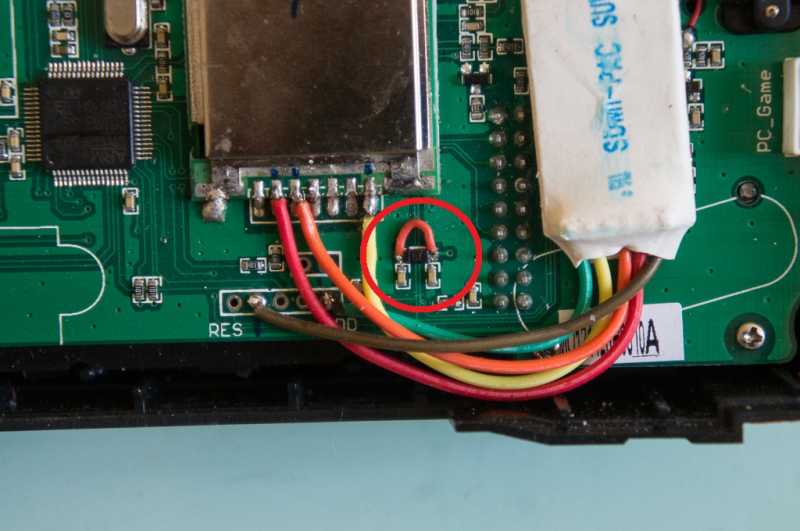
The 7e uses a double sided PCB. At times it is not possible to layout a circuit trace without crossing over. Some low end product would just use a jumper wire while the more formal ones would employ a SL for a tidy look (you can clearly see two traces running under the SL in the close up photo). It is also possible that the designer uses it as a fuse, but seems not likely in this case, but who knows..
There is nothing wrong with 7e's antenna element. It is the rigid case that matters. Antenna orientation in its stock position is the worse for R/C flying. As PB has pointed it out somewhere, the donut radiation pattern is the best when the antenna is perpenduclar to the R/C vessle (that is about 60 degress pointing up in usual flying) for maximum range. With the mod, I can choose one that can be pointed anywhere as desire...
For information, one time while I performed a range test with a boat, different orientation makes a difference of 1mW to 3mW, and the difference is consistant, that is, repeatable..
Soldering is to the tip and ground on the RF module, extended to a SMA RF socket..
Replied by cmpang on topic No RF power from 7e
Mullson wrote: What do you think the SL is there for in the first place? Maybe a stupid question.
With your antenna mod have you noticed any improvements? It only uses one soldering point no GRD or power?
The 7e uses a double sided PCB. At times it is not possible to layout a circuit trace without crossing over. Some low end product would just use a jumper wire while the more formal ones would employ a SL for a tidy look (you can clearly see two traces running under the SL in the close up photo). It is also possible that the designer uses it as a fuse, but seems not likely in this case, but who knows..
There is nothing wrong with 7e's antenna element. It is the rigid case that matters. Antenna orientation in its stock position is the worse for R/C flying. As PB has pointed it out somewhere, the donut radiation pattern is the best when the antenna is perpenduclar to the R/C vessle (that is about 60 degress pointing up in usual flying) for maximum range. With the mod, I can choose one that can be pointed anywhere as desire...
For information, one time while I performed a range test with a boat, different orientation makes a difference of 1mW to 3mW, and the difference is consistant, that is, repeatable..
Soldering is to the tip and ground on the RF module, extended to a SMA RF socket..
Last edit: 06 Mar 2013 11:13 by cmpang.
- Mullson
-
- Offline
Less
More
- Posts: 114
06 Mar 2013 23:32 #7443
by Mullson
Replied by Mullson on topic No RF power from 7e
Thanks for the explanation, I get everything except "Soldering is to the tip". What do you men?cmpang wrote: Soldering is to the tip and ground on the RF module, extended to a SMA RF socket..
- cmpang
-
- Offline
Less
More
- Posts: 296
07 Mar 2013 01:06 #7445
by cmpang
we usually called the center of a coxial cable the "tip"... and the outer wire mesh is the "ground"
Replied by cmpang on topic No RF power from 7e
Mullson wrote: ...."Soldering is to the tip". What do you men?
we usually called the center of a coxial cable the "tip"... and the outer wire mesh is the "ground"
Time to create page: 0.120 seconds