- Posts: 1951
Mjx Bugs 3
- hexfet
-
- Offline
Please Log in or Create an account to join the conversation.
- C0ckpitvue 777
-
Topic Author
- Offline
- Posts: 409
Please Log in or Create an account to join the conversation.
- Blade81
-
- Offline
- Posts: 58
Please Log in or Create an account to join the conversation.
- Blade81
-
- Offline
- Posts: 58
Can anyone assist?
Please Log in or Create an account to join the conversation.
- hexfet
-
- Offline
- Posts: 1951
The three pins towards the other end may be the signals of interest (clock, chip select, and data). Can you get a picture of the other side of the board to check for connections there?
Please Log in or Create an account to join the conversation.
- Blade81
-
- Offline
- Posts: 58
Please Log in or Create an account to join the conversation.
- Blade81
-
- Offline
- Posts: 58
Please Log in or Create an account to join the conversation.
- hexfet
-
- Offline
- Posts: 1951
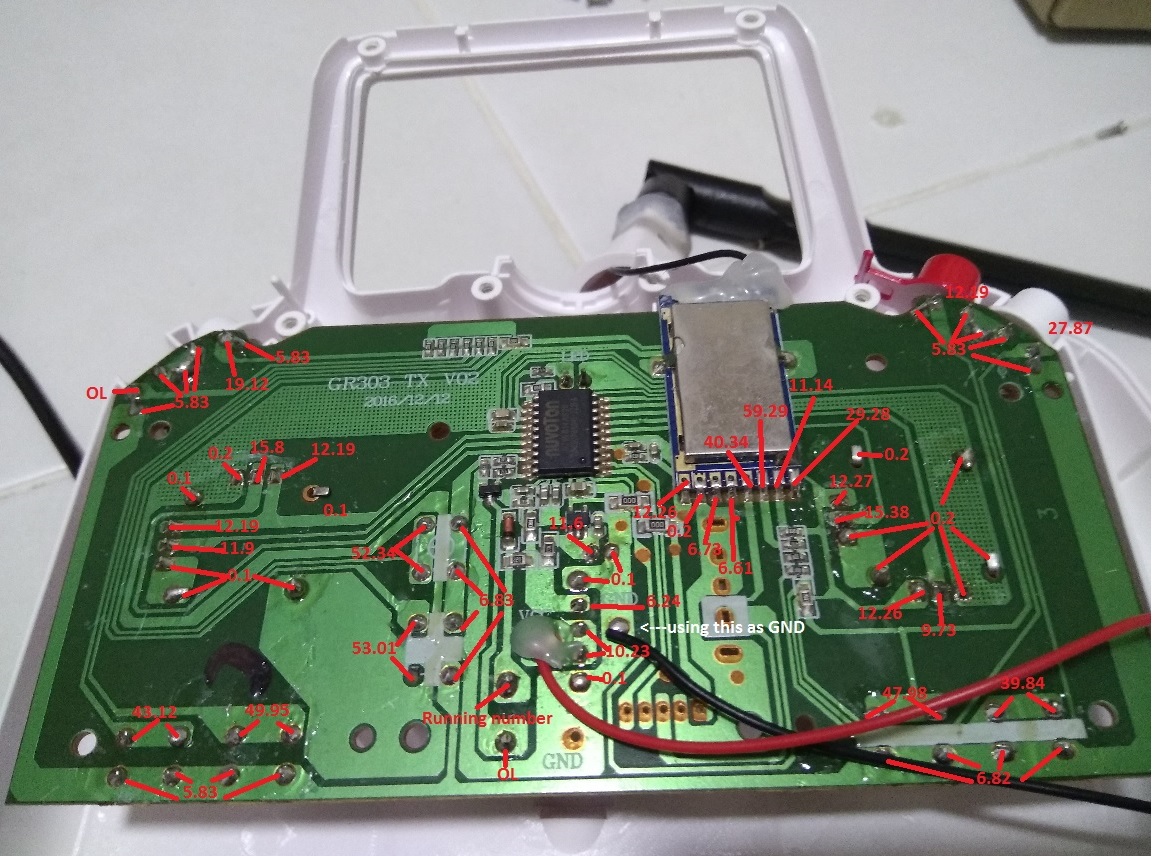
If the annotations are resistance readings to the GND black wire, it looks like pin 2 (with 1 being leftmost in picture) is a likely candidate for ground. Next step would be to turn on power to the stock tx, then measure the voltage from GND to pin 1 and pin 2 (should be about 3..3 and 0 respectively).
If that's correct, connect logic analyzer ground to pin 2, and test probe lines to pins 3 through 8. Then make a capture, triggering starting on line 3 and bumping up until the trigger fires.
Edit: The only signals that matter are the ones on the radio module.
Please Log in or Create an account to join the conversation.
- ajtank
-
- Offline
- Posts: 278
Please Log in or Create an account to join the conversation.
- Blade81
-
- Offline
- Posts: 58
hexfet wrote: What are the numbers in your annotated picture? Not sure how to ask this politely - what is your general level of electronics knowledge? I'd like to give appropriate level instructions
If the annotations are resistance readings to the GND black wire, it looks like pin 2 (with 1 being leftmost in picture) is a likely candidate for ground. Next step would be to turn on power to the stock tx, then measure the voltage from GND to pin 1 and pin 2 (should be about 3..3 and 0 respectively).
If that's correct, connect logic analyzer ground to pin 2, and test probe lines to pins 3 through 8. Then make a capture, triggering starting on line 3 and bumping up until the trigger fires.
Edit: The only signals that matter are the ones on the radio module.
I work in IT, but am an idiot in electrical
I understand the concept of intercepting the data packet that flows in and out of the tx, is to first identify which channel is sending what data packet.
First is to identify the channels by its pin layout, the standard channels runs at a standard operating voltage, more or less.
so by running continuity, from the ground, is to identifying the (nearest) ground pad to get accurate reading when performing the voltage readings from the individual pads.
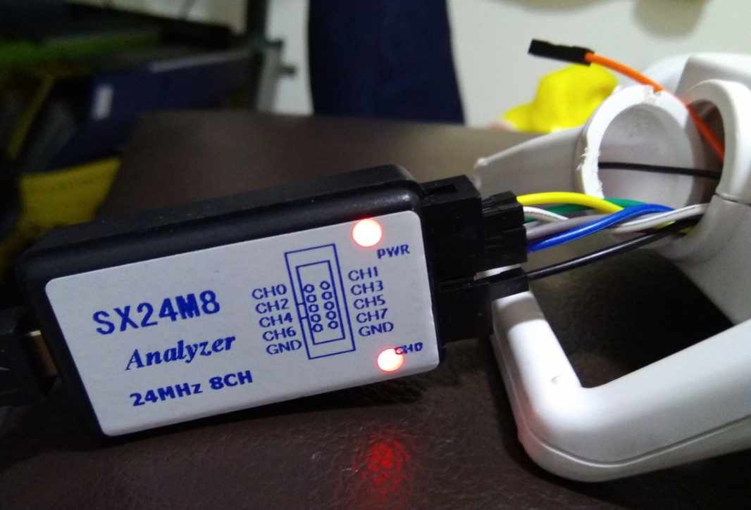
Perform voltage reading, identify the channels based on voltage readers, soldering the pins, connecting to the correct ports on the spi analyser, running the program to capture those data for "decoding" or "reverse engineering"
I happen to have few good electrical technician friends/colleagues in the company I work in so I borrowed their dmm and ask them how to use it.
But their DMM apparently is those expensive professional type and has too many options.
on top of it, I have no idea how to operate the multimeter but they guide me how to do that exactly base on serbydocky's video in the how to capture spi guide without having me drown in the pool of electrical knowledge lol
if u ask me what is dc what is ac, what is ohm, I rather you kill me LOL
so The numbers in the first picture are resistance readings, with the DMM in continuity mode.
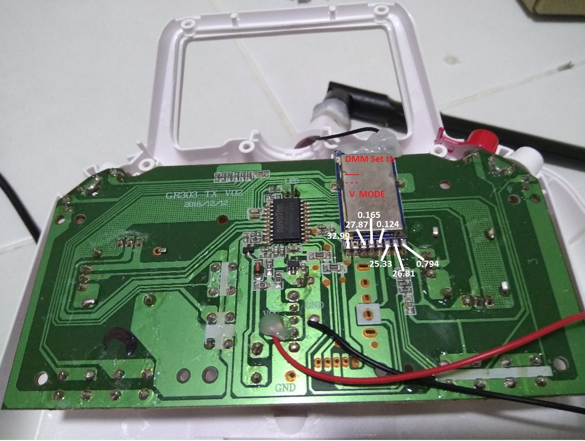
the 2nd picture is DMM in DC mode, checking the voltage readings of the pins, using the 2nd pad as ground. but I misread some of their decimal points.
which I was laughed at by my colleague when I told him my bugs 3 controller has a pad running 33v. he is like, bro you tx only uses 4 AA batteries, it cant be 33v LOL
I got my colleague to check and we went through with a 2nd reading. below is the updated readings.
Now I just need to know which pin to solder and plug to which channel on the spi analyser and I should be able to perform the capture.
sorry for being such a pain here and thank you for your patience and guide
Please Log in or Create an account to join the conversation.
- hexfet
-
- Offline
- Posts: 1951
Please Log in or Create an account to join the conversation.
- Blade81
-
- Offline
- Posts: 58
Please Log in or Create an account to join the conversation.
- hexfet
-
- Offline
- Posts: 1951
Please Log in or Create an account to join the conversation.
- Blade81
-
- Offline
- Posts: 58
let me know if there is anything else i can help
Thank you!!
Please Log in or Create an account to join the conversation.
- hexfet
-
- Offline
- Posts: 1951
Unless someone has an A1 version to test with I don't intend to continue trying to implement that variation. When I ordered the A2 receiver the A1 was shown as an option but selecting it changed the status to "no longer available".
Please Log in or Create an account to join the conversation.
- davdrone1
-
- Offline
- davdrone1
- Posts: 91
Unable to bind either model. No sign of any communication.
Time flies like a banana
Please Log in or Create an account to join the conversation.
- Blade81
-
- Offline
- Posts: 58
Btw, i must mention that bug3 original TX has few features that could prohibit us to arm too.
example, does not arm Unless throttle stick is all the way down.
disarm requires long press of the red button,
continuous short Beeps when it goes low RSSI
continuous short Beeps when quad is turn off while tx is still on
continuous long beeps when battery is low
the red button, is used for binding, arming, disarming.
bind sequence requires this red button to be hold down while powering up
Please Log in or Create an account to join the conversation.
- davdrone1
-
- Offline
- davdrone1
- Posts: 91
Should I try to do this, to improve the chances of a bind?
Time flies like a banana
Please Log in or Create an account to join the conversation.
- hexfet
-
- Offline
- Posts: 1951
The frequency tuning is worth a try. I haven't needed it with my hubsan or V911.
Please Log in or Create an account to join the conversation.
- hexfet
-
- Offline
- Posts: 1951
Please Log in or Create an account to join the conversation.
-
Home

-
Forum

-
Development

-
Protocol Development

- Mjx Bugs 3


