- Posts: 41
- Forum
- News, Announcements and Feedback
- Feedback & Questions
- Issues Adding 2x 3-way switches to devo 7e
Issues Adding 2x 3-way switches to devo 7e
- jacklscott3
-
Topic Author
- Offline
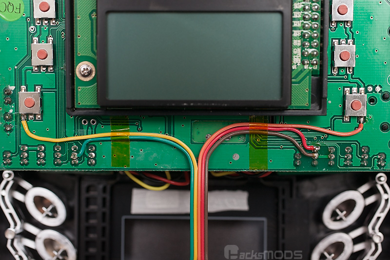
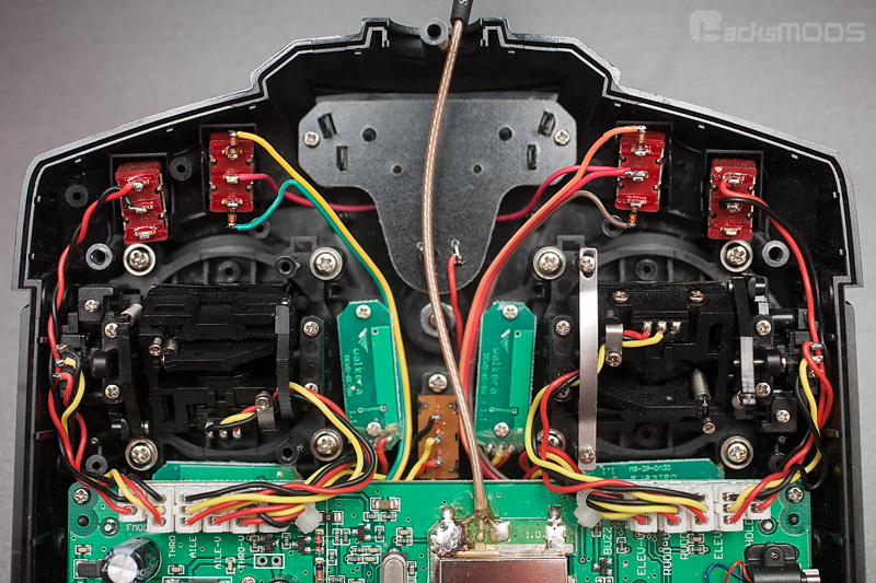
I have been working on adding 3-way switches to my devo 7e, but I haven't found much information on how to do that. I wired in my switches yesterday using a photo I found on HacksMods. However, when I turned the controller on to check my work, it was going effin BONKERS! It started making the sound it makes if you set up beeps on your throttle stick, progressively higher pitched beeps.. And the screen was not showing the normal display. It had the safety throttle location screen up, and the selection buttons were completely not working. I figured I had a short somewhere so I went back and tried wiring one of the switches again and just removed the other for the time being, but still when I turned on the transmitter I found the same haywire response. I then became a bit nervous, because I've modded the crap outta this little 7e ( installed cc2500 pa module to fly my skyartec heli's , nrf24l01 module to fly my WL toys birds, increased the range.. Basically all the mods I could find to do) and through all of that I've never NEVER seen it go crazy like that. So I removed the solder points and decided to wait until I have further information on installing the switches. When I removed the switches the tx went back to normal thankfully. But now I'm just a little nervous about trying it again. Any suggestions???
One thing I just realized Is the picture does not have a black wire on the left switch.. at the time I just assumed he was showing you how to hook up a 2 way switch and a 3way switch and that if you wanted a 3way on the left you just needed to mirror the position of your black wire on the right.. So that's a possible reason for my issue..
Also there were no clear markings on the switches themselves to indicate what port was negative, positive and such. I just looked at the factory devo switches and installed them with the similar markings going the same way. This is another possible reason for my problem
Finally, I didn't do the best job managing the wiring coming out from under the circuit board. The picture shows a cleanly taped wire that would come out somewhere in the center of the board, my wire basically came out right at the the solder points. Maybe it was pressing into something it shouldn't have??
Any help would be appreciated!!!!
On another note, once I do install these switches can anyone point me in the right direction to find out the programming side of this mod? How do I activate and implement the new switches??
Please Log in or Create an account to join the conversation.
- Arakon
-
- Offline
- Posts: 305
As for the wire routing, if they're long enough, you can carefully guide them around the transmitter module and out the top to the switches.
Please Log in or Create an account to join the conversation.
- aMax
-
- Offline
- Posts: 776
of one switch and then from there, to the midpoint of the second switch.
Edit: ..you beat me to it...
Devo7e, TaranisQ X7, R9M , 4in1 MM, Futaba FC18plusV3.2 & DFT/FLD-02
Please Log in or Create an account to join the conversation.
- Daryoon
-
- Offline
- Posts: 260
Please Log in or Create an account to join the conversation.
- jacklscott3
-
Topic Author
- Offline
- Posts: 41
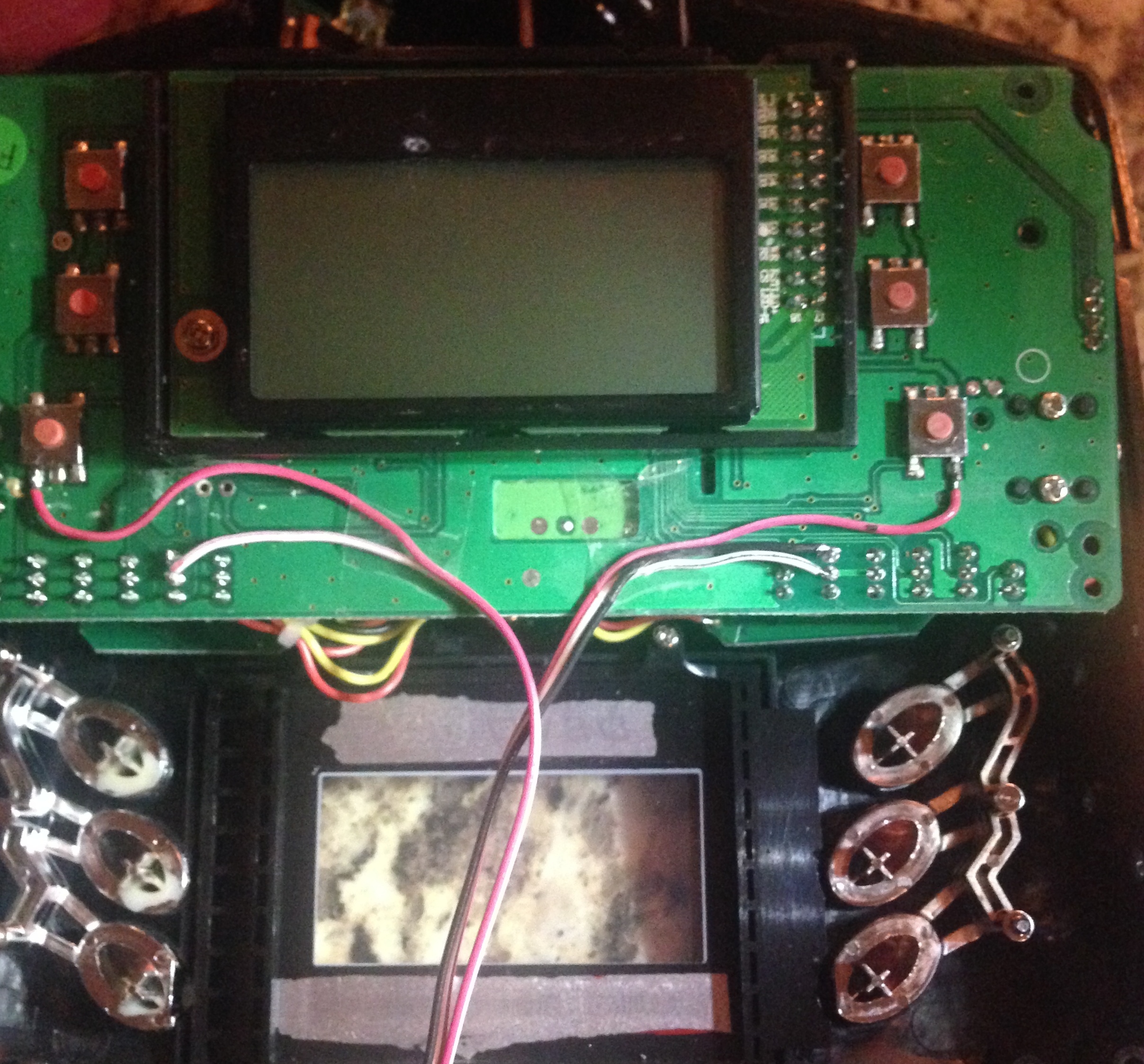
So I started over, and wired into the board first. I'm following the layout I got from hackmods, but I'm worried because I see a recent switch installation walk through on here that is different. I just know the hackmods guide says it's for installations of 3 way switches, and the guide I found on here doesn't specify. So if I'm wired into the board correctly, how exactly do I hook into the switches and where will I place the diodes?
I'm just confused because I found this:
deviationtx.com/forum/how-to/1436-add-tw...tches-to-the-devo-7e
Which is totally different from the directions I was following. So if I'm adding 3-way switches will those directions^^^ also apply for me??
Please Log in or Create an account to join the conversation.
- jacklscott3
-
Topic Author
- Offline
- Posts: 41
-red wires to the top post with diodes before the post.
-white wires to the bottom post, with diodes before the post also
-then the one black wire from the board will run up to the middle post on the right switch with a patch to the middle post on the left switch. do those need diodes?
Please Log in or Create an account to join the conversation.
- Arakon
-
- Offline
- Posts: 305
Your setup sounds correct to me. Middle pin needs no diodes. Make sure you get the direction of the diodes right, the black indicator should face to the switch pin, away from the wire.
Please Log in or Create an account to join the conversation.
- jacklscott3
-
Topic Author
- Offline
- Posts: 41

I'm not very familiar with diodes, so I have no idea if these can be utilized.
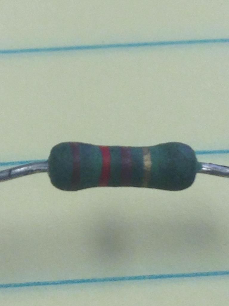
But either way I have some 1N4001 diodes (50v 1A) coming in the mail, which were recommended by one of the guides.
Just out of curiosity why do you need diodes on the switches? What purpose do they serve?
Also I looked for the hardware.ini file the last time I had my transmitter plugged into my computer and I did not see it. Where is it located?
Please Log in or Create an account to join the conversation.
- D_an_W
-
- Offline
- Posts: 101
*** Walkera Devo 10 * 4-in-1 Module * Deviation v5 *** *** Walkera Devo 7E * A7105 Module * 2x 3 Way Switches * Power Mod * Deviation v5 ***
Please Log in or Create an account to join the conversation.
- jacklscott3
-
Topic Author
- Offline
- Posts: 41
Please Log in or Create an account to join the conversation.
- Arakon
-
- Offline
- Posts: 305
The diodes are needed for the very reason you had issues before.. otherwise the buttons will trigger randomly cause the connection flows both ways.
Please Log in or Create an account to join the conversation.
- jacklscott3
-
Topic Author
- Offline
- Posts: 41
Please Log in or Create an account to join the conversation.
- D_an_W
-
- Offline
- Posts: 101
HOLD0/1 (Original Switch)
SW A0/1/2 (New 3 Way)
SW B0/1/2 (New 3 Way)
FMODE0/1 (Original Switch)
This is the Hardware.ini file (I have the power mod and A7105 module also)...
;Only useful for transmitters with an after-market vibration motor
;enable-haptic=1
;
;switch_types: 3x2, 3x1, 2x2
extra-switches=3x2
;
[modules]
; there is no need to enable the cyrf6936 module unless
; it is wired to an alternate port. It is Enabled automatically otherwise
; enable-cyrf6936 = B12
has_pa-cyrf6936 = 1
enable-a7105    = A13
has_pa-a7105    = 1
; enable-cc2500   = A14
; has_pa-cc2500   = 1
; enable-nrf24l01 = A14
; has_pa-nrf24l01 = 1
; enable-multimod = A13
*** Walkera Devo 10 * 4-in-1 Module * Deviation v5 *** *** Walkera Devo 7E * A7105 Module * 2x 3 Way Switches * Power Mod * Deviation v5 ***
Please Log in or Create an account to join the conversation.
- jacklscott3
-
Topic Author
- Offline
- Posts: 41
I had a nrf24l01 installed and a cc2500 module installed before I upgraded my firmware to the nightly builds, so I thought maybe it had something to do with that. But even when I removed them I still get the message. I tried editing the hardware.ini file and the tx.ini file ever different way I could think of, but I could not get that message to go away. I even tried removing the nightly builds fw and re-installing the old version i was running, but I still got "Bad/missing" protocol modules!"
could it be the wiring for the 3way switches? If its not that, Im out of ideas
Please Log in or Create an account to join the conversation.
- Arakon
-
- Offline
- Posts: 305
It's not the wiring.
Please Log in or Create an account to join the conversation.
- T.N.
-
- Offline
- Posts: 20
Left switch: SWA0, SWA1 then SWB2
Right switch: SWB0, SWB1 then SWA2
I checked the wriring are exactly as in the photos.
Comments are appreciated.
Please Log in or Create an account to join the conversation.
- Forum
- News, Announcements and Feedback
- Feedback & Questions
- Issues Adding 2x 3-way switches to devo 7e
-
Home

-
Forum

-
News, Announcements and Feedback

-
Feedback & Questions

- Issues Adding 2x 3-way switches to devo 7e


