- Posts: 62
Schematics of the transmitter main board
- Texacate
-
Topic Author
- Offline
Less
More
25 Apr 2017 05:34 - 26 Apr 2017 02:55 #61750
by Texacate
Schematics of the transmitter main board was created by Texacate
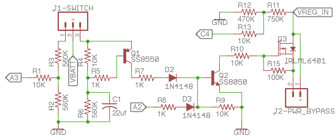
Has anyone reverse engineered (partially reverse engineered) the main boards on the Walkera Devo transmitters and created schematics ?
I'm currently interested in the power supply section on a Devo7E. The main board on mine is labeled Devo6F v2.0. The RF module soldering pads to the ARM processor connections would be very interesting too.
I'm currently interested in the power supply section on a Devo7E. The main board on mine is labeled Devo6F v2.0. The RF module soldering pads to the ARM processor connections would be very interesting too.
Last edit: 26 Apr 2017 02:55 by Texacate.
Please Log in or Create an account to join the conversation.
- Texacate
-
Topic Author
- Offline
Less
More
- Posts: 62
26 Apr 2017 02:47 - 26 Apr 2017 02:53 #61783
by Texacate
Replied by Texacate on topic Schematics of the transmitter main board
Just FYI, I'm have been taking a multimeter on my Devo7E to discover the interconnect, (at least for the larger thru-hole and surface mount components), drawing up a schematic with pencil and paper. Will probably take the board out of the transmitter shell again so I can probe some of the backside, but the LCD display obscures much of the traces on the backside. And if I get really ambitious, I'll capture the schematic into a real CAD program. Will post the a partial schematic if I can trace out all the power related circuitry.
But if someone has already done this... it would save a bunch of work!
Clearly bits and pieces of the 7E have been mapped out by the community, else we would not be able to do all the cool hardware mods; like adding a 4in1, or new toggle switches. Just wondering of anyone has drawn/shared schematics.
Last edit: 26 Apr 2017 02:53 by Texacate.
Please Log in or Create an account to join the conversation.
- silpstream
-
- Offline
Less
More
- Posts: 244
29 Apr 2017 12:18 - 29 Apr 2017 12:21 #61844
by silpstream
Replied by silpstream on topic Schematics of the transmitter main board
I did the power portion a while back for the 7e. Here it is. For details of the other pins, you should also look here to get started (if you haven't already):
https://www.deviationtx.com/wiki/hardware/devo7e
Last edit: 29 Apr 2017 12:21 by silpstream.
Please Log in or Create an account to join the conversation.
Time to create page: 0.044 seconds
-
Home

-
Forum

-
General

-
General Discussions

- Schematics of the transmitter main board

