
- Posts: 7
NoName MCU + LT89xx and Arduino + LT89xx
- Kartellinni
-
Topic Author
- Offline
Less
More
06 Feb 2023 11:27 #78219
by Kartellinni
NoName MCU + LT89xx and Arduino + LT89xx was created by Kartellinni
Hello!
Please help with connecting two LT89XX chips
I'm new at this, so please don't be too hard on me.
There is an unknown control panel from the machine, it works on an unknown microcontroller (16-foot microcircuit with the following power supply: pin 5 - GND, pin 12 - +3.3 volts. The rest of the legs are occupied Gas, steering wheel, etc.
When the remote control is turned on, the remote control is in the device binding mode, which is signaled by alternately flashing LEDs.
At first I tried to scan the signal over the air using the NRF24, but it didn’t work out for me, I managed to find out only on which channels the remote control transmits the signal.
Next, I ordered the LT89XX chip as an XY-WA module for Arduino.
With the help of a logic analyzer, I connected to the SPI of the console and read into which registers and what was written. I compared it with the datasheet and made changes to the arduino sketch written for the LT89XX, writing the same values to the registers as in the remote control.
Next, I launched the remote and the receiver and received data on the serial port, but this data is static and apparently does not relate to the data that the remote should send when you press the gas and steer. The remote also did not exit the binding mode.
I'm guessing I have to send something to the remote for the binding to happen, but I can't figure out what I should send. When I try to send what the remote control sent me, the remote control disables the binding mode (Perhaps it just turns off the indication or goes to sleep), but I don’t receive anything else from the remote control to the serial port. And the values transmitted by SPI to register 50 are changed to new ones.
The channel is also constantly changing, in increments of 20 units. For example: It starts from channel 10, then 30, then 50, then 70 and again channel 10.
After the initialization of the LT89XX, the following happens, this is written to registers unknown to me via SPI:
0x88 0x00 0x00, 0xAC 0x00 0x00, 0xAD 0xFF 0xFF, 0xB2 0x00 0x00, 0x34 0x80 0x80.
Further, the following is written in register 50:
0x32 0x06 0x24 0x0B 0xDE 0x6A 0x45 0x05
Almost the same I get in the serial port, only without 0x06
Packet read OK
Data 0 = 36 | Data 1 = 11 | Data 2 = 222 | Data 3 = 106 | Data 4 = 69 | Data 5 = 5
Next, the channel changes by writing to the register 7 new data
0x07 0x01 0x1E
And 7 times there is a record in the register 0xB0
0xB0 0x00 0x00 (x7 times)
After it all starts with a new entry in register 0x34
0x34 0x80 0x80
And so endlessly.
If I send to bullets what he sent me or part of what he sent me, then the data in register 7 and register 50 change.
New values are already being written to register 50
0x32 0x06 0x80 0x7F 0xFE 0xFF 0x00 0x06
Data 0 = 128 | Data 1 = 127 | Data 2 = 254 | Data 3 = 255 | Data 4 = 0 | Data 5 = 6
Channels 10, 30, 50, and 70 are changed to other channels, such as 21, 41, 61, and 248, and the binding indication is turned off, but no data is sent to the serial port anymore.
Below I have attached a datasheet, and a capture from saleae logic.
I do not know if I was able to describe correctly all the actions and processes that I performed and received, if additional information is needed, I am ready to provide everything.
If you have the opportunity and time to help me, I will be very grateful. I just don't know where to go next.
Sketch Arduino
The Session 0.txt file needs to change the extension to sal
Please help with connecting two LT89XX chips
I'm new at this, so please don't be too hard on me.
There is an unknown control panel from the machine, it works on an unknown microcontroller (16-foot microcircuit with the following power supply: pin 5 - GND, pin 12 - +3.3 volts. The rest of the legs are occupied Gas, steering wheel, etc.
Warning: Spoiler!
[ Click to expand ]
[ Click to hide ]
Pin 1 MCU - CLK (pin 16) LT89XX
Pin 2 MCU - SS (pin 14) LT89XX
Pin 16 MCU - MOSI (pin 1) LT89XX
Pin 14 MCU - MISO (pin 2) LT89XX
Pin 13 MCU - RST (pin 4) LT89XX
Pin 12 PKT LT89XX - Not used
Pin 2 MCU - SS (pin 14) LT89XX
Pin 16 MCU - MOSI (pin 1) LT89XX
Pin 14 MCU - MISO (pin 2) LT89XX
Pin 13 MCU - RST (pin 4) LT89XX
Pin 12 PKT LT89XX - Not used
When the remote control is turned on, the remote control is in the device binding mode, which is signaled by alternately flashing LEDs.
At first I tried to scan the signal over the air using the NRF24, but it didn’t work out for me, I managed to find out only on which channels the remote control transmits the signal.
Next, I ordered the LT89XX chip as an XY-WA module for Arduino.
With the help of a logic analyzer, I connected to the SPI of the console and read into which registers and what was written. I compared it with the datasheet and made changes to the arduino sketch written for the LT89XX, writing the same values to the registers as in the remote control.
Next, I launched the remote and the receiver and received data on the serial port, but this data is static and apparently does not relate to the data that the remote should send when you press the gas and steer. The remote also did not exit the binding mode.
I'm guessing I have to send something to the remote for the binding to happen, but I can't figure out what I should send. When I try to send what the remote control sent me, the remote control disables the binding mode (Perhaps it just turns off the indication or goes to sleep), but I don’t receive anything else from the remote control to the serial port. And the values transmitted by SPI to register 50 are changed to new ones.
The channel is also constantly changing, in increments of 20 units. For example: It starts from channel 10, then 30, then 50, then 70 and again channel 10.
Warning: Spoiler!
[ Click to expand ]
[ Click to hide ]
The transmitter operates at 62.5Kbps
Register 44 - 0x2C 0x1000 - 10: 62.5Kbps
Register 45 - 0x2D 0x0552 - Best value is 0552H when data rate is 62.5Kbps
The settings are as follows:
Register 41 - 0x29 = 0xB000
15=1, 14=0, 13=1, 12=1, 11=0, 10=0, 9:8=00, 7:0=00000000 15 CRC_ON
- 1: CRC on.
14 SCRABLE_ON -Removes long patterns of continuous 0 or 1 in transmit data. Automatically restores original unscrambled data on receive.
- 0: scramble off.
13 PACK_LENGTH_EN
- 1: LT8910 regards first byte of payload as packet length
descriptor byte.
12 FW_TERM_TX
- 1: When FIFO write point equals read point, LT8910 will terminate TX when FW handle packet length.
11 AUTO_ACK
- 0: After receive, do not send ACK or NACK; just go to IDLE.
10 PKT_FIFO_POLARITY
- 0: Active high
9:8 (Reserved)
7:0 CRC_INITIAL_DATA - Initialization constant for CRC calculation.
Register 35 - 0x23 0x0500
15=0, 14=0, 13=0, 12=0, 11:8=0101(5), 7=0, 6:0=0
15 POWER_DOWN
0: Leave power on.
14 SLEEP_MODE
0: Normal (IDLE) state.
13 (Reserved)
12 BRCLK_ON_SLEEP
0: crystal stops during sleep mode.
Saves current but takes longer to wake up.
11:8 RE-TRANSMIT_TIMES (5 times)
Max. re-transmit packet attempts when auto_ack function is enabled.
7 MISO_TRI_OPT
0: MISO is tri-state when SPI_SS=1.
6:0 SCRAMBLE_DATA
Whitening seed for data scramble. Must be set the same at
both ends of radio link (Tx and Rx).
Register 32 - 0x20 0x4800
15:13 = 010, 12:11 = 01, 10:8 = 000, 7:6 = 00, 5:4 = 00, 3:1 = 000, 0 = 0" 15:13 PREAMBLE_LEN
010: 3 bytes
12:11 SYNCWORD_LEN
01: 32bits, {Reg39[15:0],Reg36[15:0]
10:8 TRAILER_LEN
000: 4 bits
7:6 DATA_PACKET_TYPE
00: NRZ law data
5:4 FEC_TYPE
00: No FEC
3:1 BRCLK_SEL
Selects output clock signal to BRCLK pin:
3'b000: keep low
0 (Reserved)
Register 7 - 0x07 0x010A
15:9 = 0000000, 8 = 1, 7 = 0, 6:0 = 0001010 (10)
15:9 (Reserved)
8 TX_EN - 1
7 RX_EN - 0
6:0 RF_PLL_CH_NO [6:0] - 0001010 (10)
After the initialization of the LT89XX, the following happens, this is written to registers unknown to me via SPI:
0x88 0x00 0x00, 0xAC 0x00 0x00, 0xAD 0xFF 0xFF, 0xB2 0x00 0x00, 0x34 0x80 0x80.
Further, the following is written in register 50:
0x32 0x06 0x24 0x0B 0xDE 0x6A 0x45 0x05
Almost the same I get in the serial port, only without 0x06
Packet read OK
Data 0 = 36 | Data 1 = 11 | Data 2 = 222 | Data 3 = 106 | Data 4 = 69 | Data 5 = 5
Next, the channel changes by writing to the register 7 new data
0x07 0x01 0x1E
And 7 times there is a record in the register 0xB0
0xB0 0x00 0x00 (x7 times)
After it all starts with a new entry in register 0x34
0x34 0x80 0x80
And so endlessly.
If I send to bullets what he sent me or part of what he sent me, then the data in register 7 and register 50 change.
New values are already being written to register 50
0x32 0x06 0x80 0x7F 0xFE 0xFF 0x00 0x06
Data 0 = 128 | Data 1 = 127 | Data 2 = 254 | Data 3 = 255 | Data 4 = 0 | Data 5 = 6
Channels 10, 30, 50, and 70 are changed to other channels, such as 21, 41, 61, and 248, and the binding indication is turned off, but no data is sent to the serial port anymore.
Below I have attached a datasheet, and a capture from saleae logic.
I do not know if I was able to describe correctly all the actions and processes that I performed and received, if additional information is needed, I am ready to provide everything.
If you have the opportunity and time to help me, I will be very grateful. I just don't know where to go next.
Sketch Arduino
Warning: Spoiler!
[ Click to expand ]
[ Click to hide ]
/*
 * 收信机
 * 迷你强
 * chenglei1234@gmail.com
   Copyright (C) 2016 迷你强增补
 Copyright (C) 2015 Rob van der Vee"));rob.c.veer@gmail.com>

 This program is free software; you can redistribute it and/or
 modify it under the terms of the GNU General Public License
 version 2 as published by the Free Software Foundation.
 */

/* Connections:

 OCROBOT -> LT8910

 GND        GND
 3v3        VCC
 23         PKT
 21         CS
 24         RST
 11         MOSI
 12         MISO
 13         SCK

*/

#include <SPI.h>
#include "LT8900.h"

const uint8_t PIN_NRF_RST = 6;
const uint8_t PIN_NRF_CS = 5;
const uint8_t PIN_NRF_PKT = 4;


LT8900 lt(PIN_NRF_CS, PIN_NRF_PKT, PIN_NRF_RST);

uint8_t a = 6;
uint8_t b = 36;
uint8_t c = 11;
uint8_t d = 222;
uint8_t e = 106;
uint8_t f = 69;
uint8_t g = 5;

uint8_t data[] = { a, b, c, d, e, f, g };

void setup()
{

  Serial.begin(9600);
  Serial.println(F("\n\nLT8900 module sample, v0.1.\n\n"));
  /*SPI*/
  SPI.begin();
  SPI.setBitOrder(MSBFIRST);
  SPI.setDataMode(SPI_MODE1);
  SPI.setClockDivider(SPI_CLOCK_DIV4);
  delay(500);
  /*2.4G*/
  lt.begin();

  lt.writeRegister(7, 0x010A); //7 = 0x010A
//  lt.writeRegister(9, 0x4800); //9 = 0x4800
  lt.writeRegister(11, 0x0008); //11 = 0x0008
  lt.writeRegister(32, 0x4800); //32 = 0x4800
  lt.writeRegister(35, 0x0500); //35 = 0x0500
  lt.writeRegister(40, 0x2102); //40 = 0x2102
  lt.writeRegister(41, 0xb000); //41 = 0xb000
//  lt.writeRegister(44, 0x1000); //44 = 0x1000 //lt.setDataRate(LT8900::LT8910_62KBPS);
//  lt.writeRegister(45, 0x0552); //45 = 0x0552 //lt.setDataRate(LT8900::LT8910_62KBPS);
  lt.setCurrentControl(15,15);
  lt.setDataRate(LT8900::LT8910_62KBPS);  //(LT8910_62KBPS,LT8910_125KBPS,LT8910_250KBPS,LT8900_1MBPS
  lt.setChannel(0x0A);  //配置信道(500khz为一个间隔从2402Mhz起)
  lt.setSyncWord(0x03805a5a03800380);  //The receiver and transmitter must be on the same channel (Default 0x03805a5a03800380)
}

void loop()
{
    if (lt.available())
    {
        uint8_t buf[32];
        int packetSize = lt.read(buf, 32);
        if (packetSize > 0)
        {
          Serial.println(F("Packet read OK"));

            for(int i = 0; i < packetSize; i++)
            {
                Serial.print("Data ");
                Serial.print(i);
                Serial.print(" = ");
                Serial.print(buf[i]);
                Serial.print(" | ");
          }
          Serial.println();
        }
        else
        {
          Serial.println(F("CRC is ERROR"));
        }
        //lt.sendPacket(data, 7);  //Sending the second digit in the number of words in the packet
        lt.startListening();
        Serial.println("Start Listening");
    }
}
The Session 0.txt file needs to change the extension to sal
Attachments:
- hexfet
-
- Offline
Less
More
- Posts: 1971
07 Feb 2023 04:22 - 07 Feb 2023 05:09 #78220
by hexfet
Replied by hexfet on topic NoName MCU + LT89xx and Arduino + LT89xx
You're doing the right things. Just receiving the data is good progress. I don't know the LT89xx nor much about Arduino but can give some general help.
Are you taking the SPI data from the transmitter (controller) or the receiver (vehicle)? Knowing this will help interpret the data.
In these protocols the timing is important. In the Arduino sketch the (commented out) transmit is done immediately after data is received. From the SPI capture it looks like the reply is sent about 800us after the end of receiving the data. This timing needs to be replicated.
You're right that the reply is not the same data that's received. Send back the same bytes that are in the SPI capture replies. Looking at the SPI data is easier after the data is exported, but for some reason when I export the capture (using logic 2.4.6) the packet ID is always zero. This may be a bug in the analyzer. Can you make a capture using version 1 of the logic analyzer software because I know that analyzer works. The attached Ruby script will format the exported data nicely but needs valid packet IDs.
edit: it's not a bug, it's a "feature" of the v2 software. A high-level analyzer must be loaded to frame the SPI data, but that data can't be exported that I can find.
Last edit: 07 Feb 2023 05:09 by hexfet.
- Kartellinni
-
- Offline
Less
More
- Posts: 7
07 Feb 2023 07:32 #78221
by Kartellinni
Replied by Kartellinni on topic NoName MCU + LT89xx and Arduino + LT89xx
Thank you very much for responding to help!
I take the data from the transmitter, since it is in it that the microcontroller is unknown to me, so I cannot control it.
Unfortunately, I don’t know anything about time, I don’t have enough knowledge in this area and the datasheet doesn’t really help me in this either, I commented out the data sending in the sketch, since there is no information yet what exactly I should send, but what I sent without result. In the arduino sketch, I can make delays by doing millis or doing micros, now I just need to understand when to do it.
If I understand correctly, then the data transmitted between devices is recorded in register 50, the so-called FIFO, if there is data in this register, the receiver receives it and clears the register, and then you can either write new data to this register and transfer it, or simply go into receive mode and wait for new data.
I will try to send the same bytes that I received and see what happens, if I understand correctly, a delay of 800 microseconds is needed? Is this delay since the data was received? And it turns out that the data that I receive is not correct at all? My first assumption was that the remote sends data from the throttle and steering, then the remote waits for a confirmation of receipt and sends new data from the throttle and steering, but since I did not send the confirmation to it, it resends the same data.
I will try to read the SPI data in another version of the program and attach it here.
The following question is also of interest, in register 50, into which data is written and read, there is the first byte that does not seem to change 0x06, and in the datasheet there is a mention that the first byte of the payload indicates the length of the payload, in my case it is 6 bytes , and then everything seems to converge, 6 bytes go. Did I understand the datasheet and the received data correctly or am I mistaken?
In arduino, when outputting to the port monitor, this very first byte is not displayed, apparently in the sketch it is automatically discarded and I see only the last 6 bytes.
0x32 0x06 0x24 0x0B 0xDE 0x6A 0x45 0x05
It is also interesting what kind of register is 0xB0, into which 0x00 0x00 are written, nothing is said about it in the datasheet.
And while writing to 0xB0, perhaps not writing, I don’t know how to call it correctly, writing or accessing the register, data comes in the opposite direction at the same time. Perhaps it was necessary to indicate in the first post that all the registers and data in them I cited are from the MOSI bus, that is, from the microcontroller to the LT98XX transmitter.
When writing to registers 0x34, 0x32, 0x07, the following data always comes in the opposite direction 0x01 0x01 0x01, when register 0xB0 is accessed, different data comes in the opposite direction, for example:
Noticed the following:
When 7 is accessed by MOSI to 0xB0 0x00 0x00 on MISO is always 0x01 0x01 0x40
When 1, 2, 3, 5, 6 are accessed by MOSHI to 0xB0 0x00 0x00 on miso 3 bytes is always the same
I take the data from the transmitter, since it is in it that the microcontroller is unknown to me, so I cannot control it.
Unfortunately, I don’t know anything about time, I don’t have enough knowledge in this area and the datasheet doesn’t really help me in this either, I commented out the data sending in the sketch, since there is no information yet what exactly I should send, but what I sent without result. In the arduino sketch, I can make delays by doing millis or doing micros, now I just need to understand when to do it.
If I understand correctly, then the data transmitted between devices is recorded in register 50, the so-called FIFO, if there is data in this register, the receiver receives it and clears the register, and then you can either write new data to this register and transfer it, or simply go into receive mode and wait for new data.
I will try to send the same bytes that I received and see what happens, if I understand correctly, a delay of 800 microseconds is needed? Is this delay since the data was received? And it turns out that the data that I receive is not correct at all? My first assumption was that the remote sends data from the throttle and steering, then the remote waits for a confirmation of receipt and sends new data from the throttle and steering, but since I did not send the confirmation to it, it resends the same data.
I will try to read the SPI data in another version of the program and attach it here.
The following question is also of interest, in register 50, into which data is written and read, there is the first byte that does not seem to change 0x06, and in the datasheet there is a mention that the first byte of the payload indicates the length of the payload, in my case it is 6 bytes , and then everything seems to converge, 6 bytes go. Did I understand the datasheet and the received data correctly or am I mistaken?
In arduino, when outputting to the port monitor, this very first byte is not displayed, apparently in the sketch it is automatically discarded and I see only the last 6 bytes.
0x32 0x06 0x24 0x0B 0xDE 0x6A 0x45 0x05
It is also interesting what kind of register is 0xB0, into which 0x00 0x00 are written, nothing is said about it in the datasheet.
And while writing to 0xB0, perhaps not writing, I don’t know how to call it correctly, writing or accessing the register, data comes in the opposite direction at the same time. Perhaps it was necessary to indicate in the first post that all the registers and data in them I cited are from the MOSI bus, that is, from the microcontroller to the LT98XX transmitter.
When writing to registers 0x34, 0x32, 0x07, the following data always comes in the opposite direction 0x01 0x01 0x01, when register 0xB0 is accessed, different data comes in the opposite direction, for example:
Warning: Spoiler!
[ Click to expand ]
[ Click to hide ]
1 MOSI call to 0xB0 0x00 0x00 - to MISO 0x02 0x37 0x0C
2 call by MOSI to 0xB0 0x00 0x00 - to MISO 0x04 0x04 0x0С
3 call by MOSI to 0xB0 0x00 0x00 - to MISO 0x05 0x0D 0x0С
4 call by MOSI to 0xB0 0x00 0x00 - to MISO 0x0D 0x0D 0x2С
5 call via MOSI to 0xB0 0x00 0x00 - to MISO 0x0D 0x0D 0x0С
6 call via MOSI to 0xB0 0x00 0x00 - to MISO 0x0F 0x0F 0x0С
7 call via MOSI to 0xB0 0x00 0x00 - to MISO 0x01 0x01 0x40
Noticed the following:
When 7 is accessed by MOSI to 0xB0 0x00 0x00 on MISO is always 0x01 0x01 0x40
When 1, 2, 3, 5, 6 are accessed by MOSHI to 0xB0 0x00 0x00 on miso 3 bytes is always the same
- Kartellinni
-
- Offline
Less
More
- Posts: 7
07 Feb 2023 16:08 #78223
by Kartellinni
Replied by Kartellinni on topic NoName MCU + LT89xx and Arduino + LT89xx
I captured and saved in multiple formats. After approximately 1 sec 890 ms, there is a change in register 50
I saved the session just in case
I saved the session just in case
Warning: Spoiler!
[ Click to expand ]
[ Click to hide ]
- Kartellinni
-
- Offline
Less
More
- Posts: 7
07 Feb 2023 16:41 - 07 Feb 2023 16:45 #78224
by Kartellinni
Replied by Kartellinni on topic NoName MCU + LT89xx and Arduino + LT89xx
I executed your script and received the file, but unfortunately I did not understand anything, I only saw that the time frames for transferring data are different.
During initialization, each register is written every 0.287 milliseconds
Next comes the entry in register 52 0.384,38,34 80 80
Next comes the entry in register 50 1.084,39,32 06 24 0B DE 6A 45 05
As far as I understand, 0.700 milliseconds pass between them
Next is the installation of the channel by entering the channel number in register 7 1.527,40,07 01 1E
And then there are empty zeros in B0 with an interval of 0.325 milliseconds and everything repeats over again.
0.271.41.B0 00 00 .02 3B 1C .3,
0.324.42.B0 00 00 .04 04 1C .3,
0.328.43.B0 00 00 .05 0E 1C .3,
0.326.44.B0 00 00 .0D 0D 1C .3
0.326.45.B0 00 00 .05 05 1C .3,
0.326.46.B0 00 00 .0F 0F 9E .3
0.325.47.B0 00 00 .00 01 00 .3,
0.355.48.34 80 80 .00 01 00 .3,
What do I need to do next?
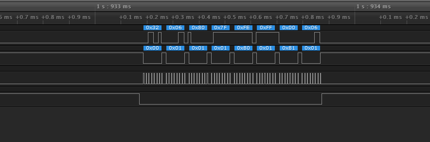
I did not find the following changes in the file, the screenshot shows changes in register 50 between 1.933 ms and 1.934 ms, I did not find this data in the file.
During initialization, each register is written every 0.287 milliseconds
Next comes the entry in register 52 0.384,38,34 80 80
Next comes the entry in register 50 1.084,39,32 06 24 0B DE 6A 45 05
As far as I understand, 0.700 milliseconds pass between them
Next is the installation of the channel by entering the channel number in register 7 1.527,40,07 01 1E
And then there are empty zeros in B0 with an interval of 0.325 milliseconds and everything repeats over again.
0.271.41.B0 00 00 .02 3B 1C .3,
0.324.42.B0 00 00 .04 04 1C .3,
0.328.43.B0 00 00 .05 0E 1C .3,
0.326.44.B0 00 00 .0D 0D 1C .3
0.326.45.B0 00 00 .05 05 1C .3,
0.326.46.B0 00 00 .0F 0F 9E .3
0.325.47.B0 00 00 .00 01 00 .3,
0.355.48.34 80 80 .00 01 00 .3,
What do I need to do next?
I did not find the following changes in the file, the screenshot shows changes in register 50 between 1.933 ms and 1.934 ms, I did not find this data in the file.
Last edit: 07 Feb 2023 16:45 by Kartellinni.
- hexfet
-
- Offline
Less
More
- Posts: 1971
09 Feb 2023 01:20 - 09 Feb 2023 01:21 #78225
by hexfet
Replied by hexfet on topic NoName MCU + LT89xx and Arduino + LT89xx
Don't have much time to dig into this. I've attached a screenshot of the script output loaded into a spreasheet. Makes it easier to look through.
Keep in mind that SPI is bi-directiional. Every byte out also reads a byte in. Since you're monitoring the transmitter MOSI is sending through the LT8900 to the rx, and MISO is data from the RX.
Like many other protocols this one first sends initialization data to the LT8900, then has a bind phase to establish a connection to the receiver, followed by a data phase if the bind is successful. You may want to look at some Deviation protocols to get the general idea. I've attached a screenshot of the script output just to give you an idea of what to look for.
This is at what seems to be the start of the data phase, at 1.933186 seconds into the trace. Usually the bytes in the middle of the packet are the channel data, with a checksum in the last byte. You'll need to reverse-engineer what all these mean if you want to make your own tx or rx.
Last edit: 09 Feb 2023 01:21 by hexfet.
- Kartellinni
-
- Offline
Less
More
- Posts: 7
12 Feb 2023 14:10 - 13 Feb 2023 08:29 #78227
by Kartellinni
Replied by Kartellinni on topic NoName MCU + LT89xx and Arduino + LT89xx
I did various experiments with the XY WB modules that have the LT8920 chip installed, using one board as a receiver and the other as a transmitter. The values of the registers used are the same as the control panel, including the length of the preamble and the sync word. The first byte written to Register 50 (FIFO) indicates the length of the payload, in my case it is 6 bytes. Data is transferred without problems, in both directions.
My transmitter is constantly cycling through channels. And in the last captures, it seemed to me that even the synchro word was changing.
I also can’t figure out the payload, according to the structure of the packet and the data written to the register, I should have this:
PREAMBLE_LEN - 3 bytes
SYNCWORD_LEN - 32 bits
TRAILER_LEN - 4 bits
CRC - 16 bits
The package looks like this:
50 6 36 11 222 106 69 5
0x32 0x06 0x24 0x0B 0xDE 0x6A 0x45 0x05
1 byte 0x32 is register address 50
2 bytes 0x06 is the payload length of 6 bytes
3,4,5 bytes 0x24 0x0B 0xDE is PREAMBLE (3 bytes)
Next, there should be a sync word consisting of 32 bits, and this, in turn, is 4 bytes, which is already not enough.
Register 50 is accessed byte by byte.
Also, after each packet sending cycle, the transmitter changes the channel by adding 20 units to the channel number, for example, it was channel 10, it became 30. And so on until it receives a packet from the receiver. After accepting the package, the channel numbers change, there was channel 10, and it became channel 21, and then there are numbers 41, 61, etc. The channel change consists of 4 cycles, then the channel numbers are repeated (10,30,50,70). I suppose that the package should contain data about changing channels to new cycles, for example, 4 bytes in the 0x0B package means 11, and the channel cycles are shifted by 11, it was 10 became 21. Also in one of the captures, I noticed changes to the register with a sync word, perhaps just a failure, or perhaps the sync word changes after each successfully delivered packet.
I couldn't get past the second batch. The transmitter stops flashing LEDs, indicating that it has bound to the receiver, but the receiver can no longer receive data from the transmitter. I added a channel change to the sketch, but this did not bring any result.
I want to try to tune the second receiver to a new package and a new channel, and play with the sync word, perhaps something will work out.
Last edit: 13 Feb 2023 08:29 by Kartellinni.
- hexfet
-
- Offline
Less
More
- Posts: 1971
16 Feb 2023 04:37 #78228
by hexfet
Replied by hexfet on topic NoName MCU + LT89xx and Arduino + LT89xx
Seems like there's some confusion between "layers of abstraction" here. The link settings for PREAMBLE_LEN, SYNCWORD_LEN, TRAILER_LEN, CRC, etc. are part of the initial chip setup. The tx and rx must both initialize their radio chips with compatible values so they can exchange data. If those are correct then data bytes can be transferred between tx and rx. Since you're able to receive data from the tx the initialization seems to be correct.
The code for these protocols generally has three segments. Initialization is first - various LT89xx registers are set to the values chosen for the radio link. Next a binding section of code establishes the data protocol link. Generally this involves the tx sending data on well-known channels and the rx responding with data that confirms it received the bind information. (In some protocols the rx does not respond at all, the bind phase just ends after a certain amount of time).
During the bind phase usually a tx specific identifier is exchanged, so the rx only binds to the given tx. Figuring out the algorithm of how this identifier is created is part of reverse-engineering the protocol.
Once bind is complete the data phase starts. The packets generally contain the bind identifier, the channel data, and a crc of some sort. Figuring out those things is the other part of being able to implement the protocol.
- Kartellinni
-
- Offline
Less
More
- Posts: 7
16 Feb 2023 08:45 #78229
by Kartellinni
Replied by Kartellinni on topic NoName MCU + LT89xx and Arduino + LT89xx
Thank you! It turns out if I receive data from the transmitter, then the binding has occurred. And the data that I can read is the payload? I have a 2-channel remote control, which means I should get only 2 values, for gas and steering. Values must be between 0 and 255, or can it be any number?
As far as I understand, the data I receive can also contain the channel number, right? Either the microcontroller already has an array of channels that it enumerates. Then either the channel change occurs when the data is acknowledged, or the channel number is transmitted in the data.
In the data that I receive
0x32 0x06 0x24 0x0B 0xDE 0x6A 0x45 0x05
The value 0x0B = 11, the next series of channels increases exactly by that much, that is, it started from 10, 30, 50, 70, the next series 21, 41, 61, 81. But this is not accurate.
- Kartellinni
-
- Offline
Less
More
- Posts: 7
16 Apr 2024 16:56 - 16 Apr 2024 17:25 #78415
by Kartellinni
Replied by Kartellinni on topic NoName MCU + LT89xx and Arduino + LT89xx
I again continued to deal with my control panel on the LT8900.
Here's what I have at the moment:
1. In binding mode, the remote control has a sync word 0x038003805a5a0380, sends the following data 06 24 0b de 6a 45 05 and changes channel approximately every 918.625 µs, channels 10, 30, 50, 70
2. Based on the received data, I sent back the same data 06 24 0b de 6a 45 05 until the bullet switched from binding mode to normal mode. This usually happens from 1st to 10th reception and transmission. I can bind the remote control only on channel 10 and 70; on channels 30, 50 I was unable to bind the remote control.
3. Next, according to the SPI, the remote control changes the channel and sync word to 0x038003805a5a0B24. And starts changing channels 21, 41, 61, 120
4. I set channel 21 and sync word 0x038003805a5a0B24 in the receiver and began receiving data from the remote control.
Then I already receive the following data
06 is the data length, 6 bytes. She is always static.
1 byte is responsible for the gas trigger
2 bytes are responsible for turning the steering wheel
3 bytes change when changing the gas trigger, steering wheel and TRIM
4 bytes Gas trim
5 bytes Steering trim
6 bytes depends on 1-5 bytes and can have the value 05, 06 or 07, depending on what ranges the first 5 bytes have from 0 to 255
Now I can receive data from the remote control, but I would like to correctly set the binding and further signal processing. Could you tell me where I should look next?
Last edit: 16 Apr 2024 17:25 by Kartellinni.
Time to create page: 0.978 seconds
-
Home

-
Forum
-
General
-
General Discussions
- NoName MCU + LT89xx and Arduino + LT89xx