- Posts: 402
Developing a universal module
- blackmoon
-
- Offline
victzh wrote: Mind you - chip select on all these chips is inverted, so it's active when LOW.
When I'm done with the layout I will publish it.
Thank you for the LOW signal CSN and sharing your design.
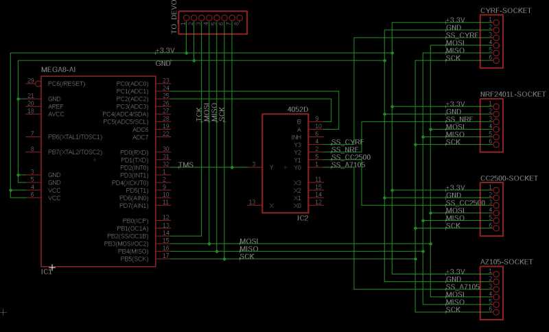
One could use a multiplexer in place of the tiny13, it was just a way to learn new stuff (really mild programing
You can not simply write the A13 and A14 in one line - this will not be recognized since only the strings "A13" and "A14" are detected - nothing else (even "a13" will not).
If you want to create a new condition like "A13+A14" you will have to change the method reading the tx.ini and the code which activates a module since all data structures and functions expect one pin to be used.
This will be no easy task.
I thought so! And as I am a nice little plant when it comes to the matter of writing code, I'll let this to Victzh's more capable hands
4 drivers for corresponding chips in src/target/common_devo/protocol
Yes the four modules Cyrf, nRF, A7105, CC2500 are really all that we need for a lot of protocols.
I would like to see an Assan (nRF24L01+) implementation, I could then use the six receiver that I have in my part box.
I think I'll have to buy that Logic Analyzer after all
Even Futaba S-FHSS is CC2500, for FASST it's ML2724 and that's another story.
Please Log in or Create an account to join the conversation.
- blackmoon
-
- Offline
- Posts: 402
Lost in translation...
Maybe is for the best
Thanks for the explanations anyway.
Please Log in or Create an account to join the conversation.
- vlad_vy
-
- Offline
- Posts: 3333
Please Log in or Create an account to join the conversation.
- victzh
-
- Offline
- Posts: 1386
@vlad_vy - yea, it's possible. It requires a bit of support on Devo's side. And I even think about placing 4 channel ADC to be able to use POTs. There are several control schemes possible, all not without trade-offs. The most realistic and least intrusive is to use TMS for the dispatcher itself and TCK as SCK routed to the currently selected device. By pushing various words in the serial shift register (analog of 595) you can activate different devices and directly set pins on devices.
It can be either implemented as 595 + 4052 (or some other multiplexer) or small CPLD. The former approach seems to be simpler, but quite rigid and limited - you can not read any extra pins, for example. The latter one is more flexible - the design is defined by a program, but I am still to master Verilog well enough to implement it. I am trying
Anyway, it is still work in progress. If you have any other suggestions, please share. @vlad_vy's one about using extra signals is very reasonable, I am afraid that some problems with CC2500 modules are because of our inability to operate these signals correctly. For power preservation it is useful practice to turn-off nRF24L01 radio with CE, for example.
Please Log in or Create an account to join the conversation.
- vlad_vy
-
- Offline
- Posts: 3333
Probably will be better to develop general purpose serial input extension board, and then connect to it various modules - RF modules, pots module, switch module, sound module and so on.
Please Log in or Create an account to join the conversation.
- FDR
-
- Offline
Please Log in or Create an account to join the conversation.
- vlad_vy
-
- Offline
- Posts: 3333
Please Log in or Create an account to join the conversation.
- rbe2012
-
- Offline
- So much to do, so little time...
- Posts: 1433
I think the easiest way of implementing additional switch logic in deviation is to use SPI to control the dispatcher.
The dispatcher would be enabled if TCK is set and get its commands. One of the command will be to activate the cyrf, another do deactivate, and so on for the other chips. Also there could be commands to let him send input values from switches / pots or whatever.
If TMS is set the spi commands are directly given to the other side of the dispatcher (only the SS signal is given only to the rf chip selected by dispatcher command).
Something like this:
Please Log in or Create an account to join the conversation.
- blackmoon
-
- Offline
- Posts: 402
victzh wrote: @blackmoon - long post is there
Assan - you mean X8, right? They also make clones of Futaba and Hitec as far as I can tell.
Yes I see that now, yesterday I couldn't see any new post made
I have an Assan X8J V2 module and 7,6,4ch receivers.
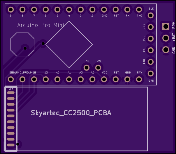
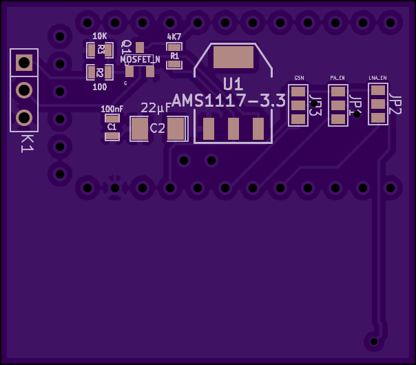
I think in the mean time, I'll just use the ppm pcb module (it's 38.38x33.68 mm should fit without issues) I designed, based on LittleMo schematic, and deviation skyartec protocol ported to arduino.
lunarflow.com/index.php?topic=8.0
And put it the devo7E plugged internally to the trainer port.
So I would have A7105, nRF24 on the spi bus and choose PPM for the skyartec wasp nano CP.
Please Log in or Create an account to join the conversation.
- PhracturedBlue
-
Topic Author
- Offline
- Posts: 4403
Please Log in or Create an account to join the conversation.
- rbe2012
-
- Offline
- So much to do, so little time...
- Posts: 1433
Maybe there are better parts like FPGA which can do this in a similar manner but I don't have any experience with such.
Please Log in or Create an account to join the conversation.
- victzh
-
- Offline
- Posts: 1386
I planned something like this, but spent last couple weeks reverse engineering and debugging Tactic SLT. I'm done with it and returning to extender.
The proposed schema is the following (mind you, I did not invent it, but learned, studying some SPI ADCs):
If you lower CSN (which can be TMS or TCK) and without clocking return it back to high, the extender recognizes it as an attention, and next SPI command goes to it. The command can switch the active device to any of RF chips, so then you communicate with them directly, using the same pin as CSN.
When the device is selected, ATMega can pass CSN signal in an interrupt handler quite fast, so no switch is needed.
Please Log in or Create an account to join the conversation.
- PhracturedBlue
-
Topic Author
- Offline
- Posts: 4403
I thought the spi ran at 4MHz. Can an Atmel chip run fast enough to do an edge-detect, and set a pin set in less than 1 cycle?
Please Log in or Create an account to join the conversation.
- victzh
-
- Offline
- Posts: 1386
Anyway, I am going to test it, and in the sad case it does not work I have a plan to use a small CPLD. I used one to recover frequency hopping for SLT (I promised myself to document it
Another (may be easier) plan is to use a switch - I know, I said it's not necessary, but may be I was too optimistic.
My initial design was a switch and a shift register - 595, but I could not design it so that in the reset state it just behaved as if it is not there, but the traditional TMS/TCK is used for a couple of RF chips. It would simplify the development because it would make hardware backward compatible with the software and one of my other goals was easiness of modification - no discreet wires, only attachment board and ribbon cable to module board, modules mounted in strict order - no room for human error.
Please Log in or Create an account to join the conversation.
- PhracturedBlue
-
Topic Author
- Offline
- Posts: 4403
I'd like to build a small board that can attach ~4 modules with an MCU and as few parts as possible to keep costs low and assembly easy.
I'd like to use a 14pin MCU with internal oscillator, which would leave 9 wires available for I/O (2supply, 3 SPI (no need for MISO)) which should allow driving >4 modules.
I was planning on using something like a pic16f1825 since I have them on hand, and they are cheap, but they cannot be programmed without a reasonably costly programmer which negates any cost-savings.
I think an ATtiny24a may be a better option as they're cheap on ebay, programmers can be had for $5 or so, and it should be possible to program directly with a Deviation Tx I think (no programmer needed)
I considered arduino (something like a micro pro), but 3.3V variants are still rare, and it would be larger than using a 14pin-PDIP. It is also overkill for just implementing a digital switch.
So I've ordered some ATTiny chips to play with. We'll see how it goes.
Please Log in or Create an account to join the conversation.
- victzh
-
- Offline
- Posts: 1386
What did you ordered?
Programming directly from Deviation is an excellent idea, by the way!
Please Log in or Create an account to join the conversation.
- PhracturedBlue
-
Topic Author
- Offline
- Posts: 4403
I don't need performance from the attiny. I can use a slow spi from the STM32 to control it (so a bit-banged interface is likely fine on the attiny if USI doesn't work for me), and I'll use an interrupt to actually toggle the I/O CSN pins.
Basically I plan touse it as a pure digital switch.
The STM32 will sends (via SPI with CSN High) something like:
set pins 1,3,5 high
set pins 2,4,6 low
set pins 8 to follow CSN
set pins 9 to follow !CSN
then just run the existing protocol code on stm32.
the attiny will watch for changes in CSN and flip the relevant output pins
This way the attiny is just a dumb switch and doesn't know anything about how the modules are hooked up. It should allow us the maximum flexibility without needing to reprogram the attiny if more transceivers are added in the future.
Have you done any work on layout for modules in the Devo7e? I am trying to decide between a board that you can solder modules to (i.e. module pin-layout is pre-wired making it almost fool-proof) vs just leaving a bunch of headers which can be wired to different modules. The former would make it easier for folks with limited skills to get it working, but requires planning of how to place the modules, limits the module choice to those with the right pin-out, and will be more expensive as the board will be larger. The 2nd would let me build a really small board, but requires more work to properly solder. I am leaning towards actually soldering the modules to the board as I think having an easy to build kit is worth it, and it means the user doesn't need to worry about securing the modules in the Tx, but it means I need a layout that can fit inside the 7e. I'll probably leave pin headers too in case different modules are chosen.
Please Log in or Create an account to join the conversation.
- blackmoon
-
- Offline
- Posts: 402
www.deviationtx.com/forum/7-development/...odule?start=40#15580
Even tough the way I thought it wasn't going to work.
This will be a nice addition to deviation.
Please Log in or Create an account to join the conversation.
- victzh
-
- Offline
- Posts: 1386
With software repeater it is a bit problematic - how tight is the timing? I understand you can set CSN and then take a small pause for signal propagation, but is it feasible in the protocol handler? It is running in interrupt time, right?
Please Log in or Create an account to join the conversation.
- PhracturedBlue
-
Topic Author
- Offline
- Posts: 4403
Please Log in or Create an account to join the conversation.
-
Home

-
Forum

-
Development

-
Development

- Developing a universal module


