
- Posts: 46
Porting Deviation to F3/F4 MCU, new LCD, etc
- cstratton
-
Topic Author
- Offline
Less
More
15 Jan 2014 21:15 #18542
by cstratton
Replied by cstratton on topic Porting Deviation to F3/F4 MCU, new LCD, etc
Thank for the confirmation on the ADC / DMA being asynchronous from the program logic.
I'm making some progress with the stand alone test... these peripherals are **very** picky about initialization order, and when that is wrong it just hangs in calibration waiting on flags that will never get set by the peripheral engine. But once I get the chip part figured out, I think it's now clear how to plug it in to deviation.
(I believe your above post about the ATTiny84 goes in the universal module thread)
- cstratton
-
- Offline
Less
More
- Posts: 46
17 Jan 2014 17:14 - 17 Jan 2014 17:17 #18589
by cstratton
Replied by cstratton on topic Porting Deviation to F3/F4 MCU, new LCD, etc
Got non-DMA ADC readings on the F3 working by taking an example against the ST libs and manually coding the necessary register operations to work around the numerous apparent omissions of the libopencm3 F3 support.
Still getting all zeros in the DMA memory buffer though, I'm going to have to go through that configuration register bit by register bit as well...
There seems to be some cyclic noise of around 10 adc counts. At some point once I get DMA up I should capture a large buffer quickly and see if I can figure out what the frequency is. I don't think the Discovery boards are particularly designed for low analog noise, and having the stlink USB be connected (and the source of power) plus a USB-UART debug cable can't be helping things.
But the real question is how much filtering I'd need to put on a custom board. I'm leaning towards assuming I'll need a series resistor (or ferrite?) and a cap to ground at each input, plus a similar filter to separate the analog supply from digital.
I was noticing the gimbal element I removed from a 1990-vintage Futaba AM transmitter only moves the pot through a portion of its range. The F3 has differential ADCs, I wonder if it would be worth playing with trying to see if running differential against a half-supply reference could get more bits from the utilized range, or just more noise.
Last edit: 17 Jan 2014 17:17 by cstratton.
- cstratton
-
- Offline
Less
More
- Posts: 46
17 Jan 2014 20:11 - 17 Jan 2014 20:26 #18599
by cstratton
Replied by cstratton on topic Porting Deviation to F3/F4 MCU, new LCD, etc
Unmounted LCDs and little buttons arrived, thinking about where they best fit and which TX to retrofit.
But also, I must admit, getting an itchy mouse finger when looking at the price of a Devo 7e. Seems like a nice little radio for just flying. And assuming there isn't much behind the CPU on the board, changing out the processor for the 256K flash version would be fairly simple with access to a hot air station. (Technically an F303 will go on an F103's PCB, but I don't think I'd push it that far, but just use the maximum memory F103)
I suppose that would never be a popular modification, but wonder if it might be useful for those doing development, to be able to get extra debug code in that won't fit in a user build?
Update: This is interesting... the 'F103 actually comes with up to a megabyte of flash in the 64PQFP. The `F303 seems to top out at 256K.
Last edit: 17 Jan 2014 20:26 by cstratton.
- PhracturedBlue
-
- Offline
Less
More
- Posts: 4403
17 Jan 2014 21:10 #18601
by PhracturedBlue
Replied by PhracturedBlue on topic Porting Deviation to F3/F4 MCU, new LCD, etc
I purchased a STM32F103RCT6 to put in my devo7e (and another for my DevoF7). I haven't gotten around to installing it yet though. The board is readily accessible, so replacing the MCU should be a easy with the right equipment.
- victzh
-
- Offline
Less
More
- Posts: 1386
17 Jan 2014 22:02 #18604
by victzh
Replied by victzh on topic Porting Deviation to F3/F4 MCU, new LCD, etc
The best way to desolder an MCU is to use Chip Quick SMD Removal Kit. It is indium based solder with very low melting point and it mixes with existing solder and makes it very easy to desolder chips with many pins. No hot air needed and it is much more reliable. You need to clean the place after removal with copper desolder braid so that no traces of indium solder left.
With new MCU Devo7e build should be very close to Devo 10, right?
With new MCU Devo7e build should be very close to Devo 10, right?
- PhracturedBlue
-
- Offline
Less
More
- Posts: 4403
17 Jan 2014 22:07 #18605
by PhracturedBlue
Replied by PhracturedBlue on topic Porting Deviation to F3/F4 MCU, new LCD, etc
A Devo7e with the 2x3way switch mod, diode fix, and an upgraded MCU would be a solid Devo10 competitor (you'd still be missing some analog/digital inputs).
Given the time required to do those mods, I'd rather spend the extra money for the Devo10.
But we shouldn't derail cstratton's thread. The work to support an 303 MCU is very nice..
Given the time required to do those mods, I'd rather spend the extra money for the Devo10.
But we shouldn't derail cstratton's thread. The work to support an 303 MCU is very nice..
- cstratton
-
- Offline
Less
More
- Posts: 46
18 Jan 2014 02:07 - 18 Jan 2014 02:55 #18611
by cstratton
Replied by cstratton on topic Porting Deviation to F3/F4 MCU, new LCD, etc
I FINALLY got the ADC DMA working.
Was puzzled for a while why I couldn't get the stick indicators on the main screen to move. Then I realized I needed to calibrate the sticks. And for that I needed buttons, so I faked them with the receive UART from my debug terminal. And then it crashed because it tried to talk to a CYRF on a non-initialed module SPI bus, so I pre-empted that...
And now I can move the one stick I wired up to the F3 discovery and have the channel indicators on the LCD move. (Hmm, but so far only on the channel monitor screen, perhaps I need a working model... the perils of trying to port software I don't yet know how to use!)
Next step... toss up between wiring up an RF module or figuring out how I want to shoehorn it into which case and if I am or am not making a custom board. But I think first I'll fly a couple batteries through the nCPx on its stock transmitter and then call it a night.
On the desoldering, I'd prefer to use the hot air station rather than get weird alloys on the board. I've seen videos of it done with chip-quick, but it's far messier than using the right tool (the hot air station) and there's one sitting at the end of the bench where I'm working on this which I make regular use of. If I had to do it one a board I couldn't remove from a plastic housing, then I might consider it though. Moot point for the moment though as I decided to hold off any more purchases (such as a devo to mod) until Monday.
Last edit: 18 Jan 2014 02:55 by cstratton.
- cstratton
-
- Offline
Less
More
- Posts: 46
19 Jan 2014 03:33 - 19 Jan 2014 03:58 #18662
by cstratton
Replied by cstratton on topic Porting Deviation to F3/F4 MCU, new LCD, etc
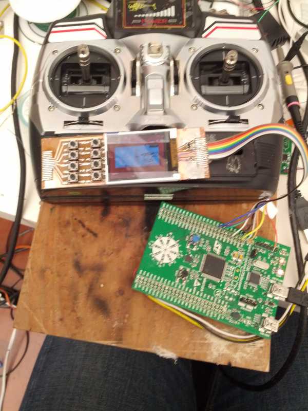
Made a board for the lcd and buttons for a TX retrofit.
I always forget how long the design stage takes. I didn't really want to put all the buttons on the left, but it simplified things for a single-layer board using toner transfer etch resist.
LCD part works, can't really see it in the picture as I left the film on to protect it during assembly, but that's the deviation 128x64 main screen centered in the unsupported-resolution LCD. I'd been a little concerned about soldering to the flex cable of the LCD but it turned out to be very easy - just tinned the pads on the board, tinned the flex, held it in place and used the iron like a little iron to merge them. Haven't hooked the buttons up yet, but I expect they'll work. I'm not sure if this assembly is a keeper to just a test platform - in theory I could 3d print a protective bezel for it or something.
Doing the processor board is going to be more time consuming - just at the very beginnings of that currently.
Last edit: 19 Jan 2014 03:58 by cstratton.
- SadSack
-
- Offline
Less
More
- Posts: 317
19 Jan 2014 11:26 #18675
by SadSack
Replied by SadSack on topic Porting Deviation to F3/F4 MCU, new LCD, etc
I did look at upgrading to STM32F103RCT6 but wasn't supported in code and not able to do it myself. Copying Devo7e is very simple, lowest part/wire needed to get running .
If another serial port could be opened and support for extra PPM in/out. Upgrading quite simple and cheap. Can use OLED 1" up to 2.9" theres even a cheap TFT screen which I'm hoping will work, once I figure out connections in code.
If another serial port could be opened and support for extra PPM in/out. Upgrading quite simple and cheap. Can use OLED 1" up to 2.9" theres even a cheap TFT screen which I'm hoping will work, once I figure out connections in code.
- PhracturedBlue
-
- Offline
Less
More
- Posts: 4403
19 Jan 2014 15:09 #18684
by PhracturedBlue
Replied by PhracturedBlue on topic Porting Deviation to F3/F4 MCU, new LCD, etc
It's cool to see deviation working on custom hardware. The 103RCT6 will work as is. Of course the whole point would be to enable language, datalog, etc and then disable module support (which would require updating the devo7e.ld file). I think the number of folks likely to make that mod is exceptionally small though.
cstratton: Can you get the discovery board in your Tx? It looks like a tight fit.
Personally, I probably would have tried something like this:
www.ebay.com/itm/STM32F103VCT6-Developme...&hash=item417b41b76a
but I admire your dedication to getting the F3 working.
cstratton: Can you get the discovery board in your Tx? It looks like a tight fit.
Personally, I probably would have tried something like this:
www.ebay.com/itm/STM32F103VCT6-Developme...&hash=item417b41b76a
but I admire your dedication to getting the F3 working.
- cstratton
-
- Offline
Less
More
- Posts: 46
19 Jan 2014 15:44 - 19 Jan 2014 15:52 #18686
by cstratton
Replied by cstratton on topic Porting Deviation to F3/F4 MCU, new LCD, etc
I could get the discovery board in if I removed all the header pins, and the tall reset & user buttons.
But I've designed lots of boards for the STM32F100, 103, and 372, so doing one for the 303 shouldn't be a problem, it's just time consuming, especially when using minimal and oversized vias for hand fabrication (I order PCB's too, but hate waiting - in fact if I do a board today I'll be transplanting the chip off a discovery)
(Speaking of which, I really should do some STM32 breakout boards and order them to have on hand - I did some TQFP48 breakouts which got a lot of use, but I did them "dumb" which means a lot of jumpering just to get the CPU going. I should do some for the 64 or 100 pin packages with the power, clock, serial, USB, etc circuits already set up which would have made them a lot more usable - and should figure out how to accomodate the handful of pins that are power on the '103 but usable I/O on the '303)
At the moment I'm indecisive between putting some dismounted gimbals in a big project box that can fit the unmodified discovery board but is unwieldy to hold as a sort of testbed, vs making a board that fits in the TX.
Probably I should do both, as I've been thinking about the 320x240 touchscreen on an F4 discovery, and that's one where I'd really want to sort out the pin assignments before doing a board.
... or maybe I'll just design and etch a spacious, flat, breakout for the 100 pin `103/`303 and sort out the rest with a soldering iron on the first copy while OSHPark makes me a few more.
Sadsack: interesting that the Crius OLED already works. I had been thinking of looking into that, but wasn't sure how fast it could go. If you were implying using PPM in from the original encoder, then it could probably be done quite compactly, using a 48pin processor on a board stacked right behind the LCD - just hook up PPM, modules, and whatever additional switches and knobs one wants to add.
Last edit: 19 Jan 2014 15:52 by cstratton.
- PhracturedBlue
-
- Offline
Less
More
- Posts: 4403
19 Jan 2014 15:58 #18687
by PhracturedBlue
Replied by PhracturedBlue on topic Porting Deviation to F3/F4 MCU, new LCD, etc
What equipment do you use for the boards? How do you deal with plating the vias? I've never gotten far enough into it to try making my own.
- cstratton
-
- Offline
Less
More
- Posts: 46
19 Jan 2014 19:48 #18706
by cstratton
Replied by cstratton on topic Porting Deviation to F3/F4 MCU, new LCD, etc
I use a an HP personal laserjet (nothing else I tried worked well), a clothes iron, and pages cut from magazines.
I hate holes.
So I really try to minimize their use in DIY prototypes. I can do really tiny vias with a wire drill in a pin vise if I have to, but try to avoid it. And I'll surface mount almost anything, inlcuding parts intended to be through hole. Connectors do take some care though, as they can rip the foil right off the board.
I've never tried to do a plated through via, I just end up putting wire wrap wire through the holes.
Likely on the STM32 prototype I'll use double sided stock but not etch the back at all - just tape it over and declare it ground, and drill through to it where needed. I might end up with a wire across the top of the processor for power, we'll see.
- cstratton
-
- Offline
Less
More
- Posts: 46
20 Jan 2014 03:09 #18736
by cstratton
Replied by cstratton on topic Porting Deviation to F3/F4 MCU, new LCD, etc
Processor board is in the etchant. A few traces broke in the transfer but hopefully fixable or unneeded... will have to see....
Getting the STM32F303 off the discovery took longer than I expected to heat with the hot air, but when it came off it came off cleanly. I wasn't sure how I was going to lift it, so ended up threading fine wire under the pins on two sides to make a sling.
Getting the STM32F303 off the discovery took longer than I expected to heat with the hot air, but when it came off it came off cleanly. I wasn't sure how I was going to lift it, so ended up threading fine wire under the pins on two sides to make a sling.
- cstratton
-
- Offline
Less
More
- Posts: 46
20 Jan 2014 05:07 #18748
by cstratton
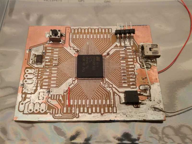
It boots and complains on the serial that it can't talk to the flash chip.
The not yet installed flash chip...
Replied by cstratton on topic Porting Deviation to F3/F4 MCU, new LCD, etc
It boots and complains on the serial that it can't talk to the flash chip.
The not yet installed flash chip...
- cstratton
-
- Offline
Less
More
- Posts: 46
21 Jan 2014 03:21 - 21 Jan 2014 03:22 #18816
by cstratton
Replied by cstratton on topic Porting Deviation to F3/F4 MCU, new LCD, etc
Minimally productive evening. For the second time I failed to hook up the ground on the flash chip (manual wire via in this case). Only this time, as I fixed it, I got smart and put in some read verification in the temporary upload program.
...and proceeded to spend an hour chasing the source of the "noise" which was causing readback to be close, but not quite right...
Actually, when I put in the read checking, I accidentally ended up with the flash address increment in the block of error code. So it would write a block, fail to increment and write another on top of it, error, and only then increment. I really should get that mass storage code working - allegedly the F3 USB peripheral is the same as the F1, so it may just copy over with minimal changes.
Board has all its bypass caps now, but is yet a bit messier from being worked on. Deviation is finding its file system image, but attaching LCD and buttons and sticks still to come.
Last edit: 21 Jan 2014 03:22 by cstratton.
- cstratton
-
- Offline
Less
More
- Posts: 46
23 Jan 2014 04:54 - 23 Jan 2014 04:58 #18969
by cstratton
Replied by cstratton on topic Porting Deviation to F3/F4 MCU, new LCD, etc
Yesterday was carve the case of the old TX day.
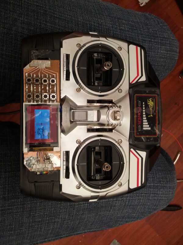
Today was wiring up the buttons and mapping them in the program. Currently six are used but I gave myself two spares, especially as there are no digital trims.
And then I decided to wire up stick pots, but only got the aileron done before running out of time. Only, no response. Hmm... Looked again and I'd wired the aileron trim, not the main pot. Moving the trim does show up in the channel monitor after calibration, so it seems good so far.
I won't have time to work on it again until next week, which is too bad because I had hoped to get it far enough to valid the basic design and order boards during the downtime. Before I do that though, I want to make sure it is workable, see if the connection would also allow for an F4, and see if I can make the form factor of the processor board match that of the LCD and buttons board, probably with the buttons on either side symmetrically. But no rush, I'm getting better at flying the nano CPX with the DX4e... Compared to a 4#3b, everything is well behaved.
Last edit: 23 Jan 2014 04:58 by cstratton.
- SadSack
-
- Offline
Less
More
- Posts: 317
02 Feb 2014 07:22 #19678
by SadSack
Replied by SadSack on topic Porting Deviation to F3/F4 MCU, new LCD, etc
The cirrus oled not worth the money there broken out the box. They tied reset to V+, so you need to add Res/cap. once done they work great but only I2c, i butchered mine to 4 wire serial. On the makers site they have all detail's needed for all interfaces so should work with 7e/10. And on your tx would you could use the Power Display Panel and put screen there! Kinda like this..
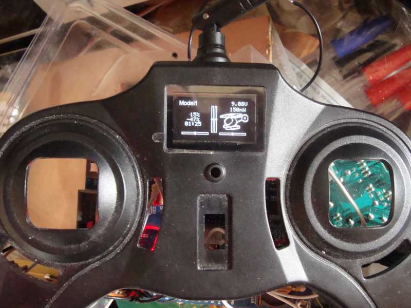
This is my fully functional knockoff devo7e") Screen speed is fine but know what you mean when i used ladyada oled demo code for arduino ran great but not a patch when connected to stm32.
Screen speed is fine but know what you mean when i used ladyada oled demo code for arduino ran great but not a patch when connected to stm32.
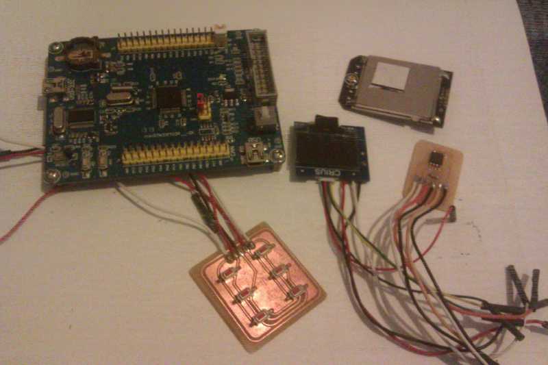
This is my fully functional knockoff devo7e
- HappyHarry
-
- Offline
Less
More
- Posts: 1136
02 Feb 2014 12:41 #19682
by HappyHarry
Replied by HappyHarry on topic Porting Deviation to F3/F4 MCU, new LCD, etc
great work bud ")
- SadSack
-
- Offline
Less
More
- Posts: 317
11 Feb 2014 21:18 #20147
by SadSack
Replied by SadSack on topic Porting Deviation to F3/F4 MCU, new LCD, etc
Well while I'm waiting thought I'd post pic of Eagle circuit for LCD.
Time to create page: 0.185 seconds
-
Home

-
Forum
-
Development
-
Development
- Porting Deviation to F3/F4 MCU, new LCD, etc