- Posts: 15
Devo 12s 3in1 / 4in1 RF module neat installation.
- Mr_W
-
- Offline
blackmoon wrote: For the 4-1, why not use the MM pcb like BirdBarber suggested and add to the Attiny source, the chunk of code needed ?
Its too big. You basically need attiny smd breakout board.
Who has the MM source code?
Please Log in or Create an account to join the conversation.
- mtx63
-
- Offline
- Posts: 37
Dieter
Please Log in or Create an account to join the conversation.
- Mr_W
-
- Offline
- Posts: 15
mtx63 wrote: the simple solution - Arduino Nano Board I / 0
Dieter
Good idea. Probably the cheapest solution.
Please Log in or Create an account to join the conversation.
- blackmoon
-
- Offline
- Posts: 402
As for the size of the MM pcb, I don't have any 4-1 module (and BG doesn't list it size) but it seems that it isn't much smaller than the MM pcb.
And it would be much simpler to install than a MM populated with three modules, I have one in my 7E and it was a pita to shoehorn it in.
Anyway, I don't really see the need to use the 4-1 in a devo tx, unless for the 7E to have CYRF long range capability, but even in that case it isn't practical, because you have to unsolder the standard devo module, and if you have to do that, why not just pop the shield off and use conductive ink to do the long range mod ?
I was going to do a mother board for the 4-1 module (+/- 1h work), but in the end it would only be another MM and without code it is a waste of time. As for the 3-1 wires are good enough to install it no need to have a board for that.
Edit: I can't locate the source code for the MM in the site, maybe it's in the deviationTX repository on github or just ask PB for it.
Please Log in or Create an account to join the conversation.
- BirdBarber
-
- Offline
- Hummingbird Assassin
- Posts: 134
blackmoon wrote: ....Anyway, I don't really see the need to use the 4-1 in a devo tx, unless for the 7E to have CYRF long range capability....
I can see using it in my 8S, it would be a safer mod because you could do much less soldering on the mainboard by making a plug for the 8S CYRF socket and run most of the wires to the plug. Also, you reduce the antenna count. You could even use the old CYRF chip enable line in place of TMS or TCK, So I think you might only need to solder one wire to the mainboard. It would be nice if the CYRF plug was right on the demultiplexer board to save wiring. You wire the 4in1 to the multiplexer, plug it into the CYRF socket, then run one wire to TMS or TCK, then hook up the existing antenna and done!
Please Log in or Create an account to join the conversation.
- Mr_W
-
- Offline
- Posts: 15
Pretty much don't care what will be the "official" way to do it, as I have my own deviationtx builds so I can make pretty much whatever combination I need. (I run some custom nrf24l01 protocols for some of my toys).
But I do intend to publish my setup, if it turns out to be neat and clean.
Please Log in or Create an account to join the conversation.
- TheSFReader
-
- Offline
- Posts: 64
But I've yet to understand the "protocol" between the devo and the attiny, and how it is implemented on both sides...
Please Log in or Create an account to join the conversation.
- blackmoon
-
- Offline
- Posts: 402
Fore bigger planes I use the 10 with only CYRF and cc2500. I also have a 6S to who I'll be adding a 3-1 since the internal cyrf is already a long range. And then the 7E will be sold.
If someone changes the MM source to accommodate the antenna switching on the 4-1, I'll do the drop in board to replace the CYRF module on the 8-6s-10, providing they have same signals on the same pins on the connector. Didn't check that though, but I'm not loosing time if no code exist. I began that some time ago...
Please Log in or Create an account to join the conversation.
- Mr_W
-
- Offline
- Posts: 15
blackmoon wrote: Yup you guys are right single antenna is cool to have, as of now in my 7E all antenna expect the Devo cyrf are internal so not a big deal for me, as it only used for micro stuff.
Fore bigger planes I use the 10 with only CYRF and cc2500. I also have a 6S to who I'll be adding a 3-1 since the internal cyrf is already a long range. And then the 7E will be sold.
If someone changes the MM source to accommodate the antenna switching on the 4-1, I'll do the drop in board to replace the CYRF module on the 8-6s-10, providing they have same signals on the same pins on the connector. Didn't check that though, but I'm not loosing time if no code exist. I began that some time ago...
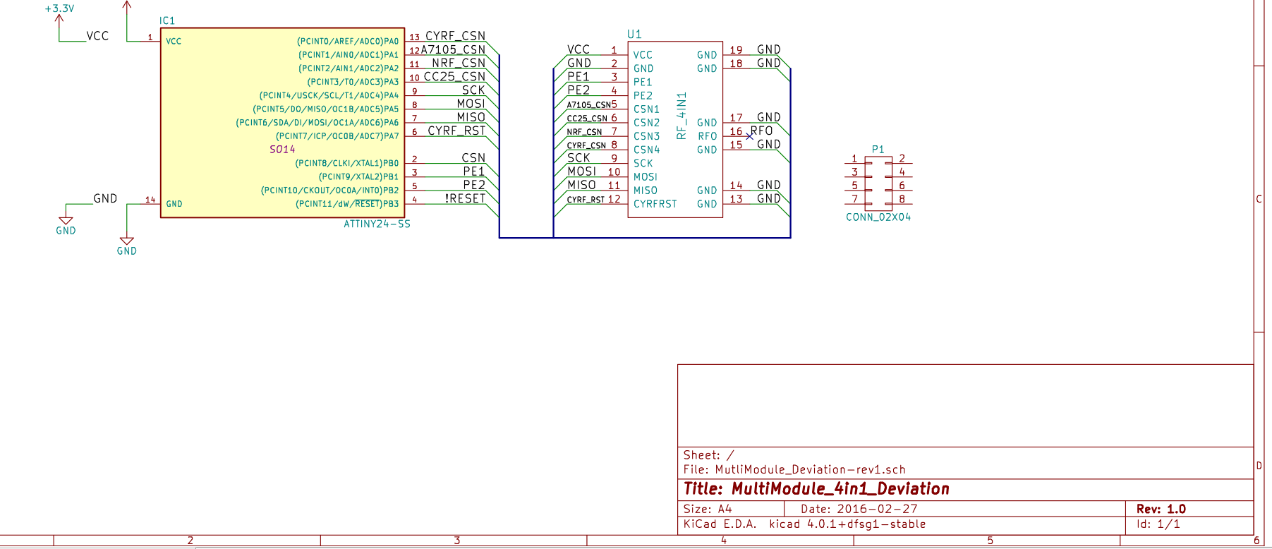
You do not actually need to route SCK, MOSI and MISO over tiny. These got directly from main mcu to 4in1.
*_CSN and PE lines need to be multiplexed.
My approach would be (when replacing onboard cyrf) to reuse original CYRF_CSN line plus two additional that are easily accessible ( TMS and TCK ). That gives 2 bits for chip select, that equal PE matrix.
Then make the tiny (or arduino nano) decode 2 lines to:
0 - CYRF_CSN low
1 - A7105_CSN low
2 - CC2500_CSN low
3 - NRF24L01_CSN low
and gated by original CYRF CSN.
Every time individual CSN line is selected, corresponding PE1/PE2 lines would be latch correct combination.
(*) I could be wrong about exact order of chip selects, but that's not important here.
Please Log in or Create an account to join the conversation.
- midelic
-
- Offline
- Posts: 174
The 4in1 module is build for multiprotocol ,It you want to see how we handled the PE1 and PE2 see the multiprotocol code.
It is very simple.The logic is posted on the BG site or multi diagram.
You can see here the code.
github.com/pascallanger/DIY-Multiprotoco...master/Multiprotocol
multiprotocol.ino.
Another thing I tested the output power of 4in1 module and multimodule with separate modules.The output is similar,tested with RF explorer spectrum analyzer wit the same antenna.The only problem is that you need to find a good antenna.
I tested several antennas including high gain ones and found them faulty or nor tuned properly.The differences can be very high.
www.rcgroups.com/forums/showpost.php?p=34517982&postcount=3516
Please Log in or Create an account to join the conversation.
- Mr_W
-
- Offline
- Posts: 15
Lets consider this - TMS & TCK lines connected directly to PE1/PE2, but also to A0 and A1 of 74HC138 chip. A2 goes to ground. Or vcc. Think about that later.
74HC138 outputs O0-O3 should be connected to _CSN lines.
And original CSN line that went to CYRF chip goes to 74LS138 E1 input. E2 goes to ground, E3 to VCC.
That way software has direct control over PE1/PE2 lines (binary) and CSN line is demultiplexed to correct output with 74HC138.
74HC138 has inverted output, which is great for CSN lines.
Please Log in or Create an account to join the conversation.
- Mr_W
-
- Offline
- Posts: 15
Please Log in or Create an account to join the conversation.
- dc59
-
Topic Author
- Offline
- Posts: 799
Is that mean, the 4in1 board design is ok? no power loss problem? or power loss is very small?
Thanks.
Please Log in or Create an account to join the conversation.
- midelic
-
- Offline
- Posts: 174
Two the same 2dB rubber duck antennas can output very different power.
However there are some design flaws which affect telemetry on A7105 and nrf 24L01 chip
Please Log in or Create an account to join the conversation.
- cmpang
-
- Offline
- Posts: 296
I would suggest to use 4 NiMH cells against 2S LiPo to reduce heat.
BTW, i have been using 1S (7e)supply for the past two years with zero problem whatsoever
Please Log in or Create an account to join the conversation.
- dc59
-
Topic Author
- Offline
- Posts: 799
Thanks for your reply, it's helpful information.
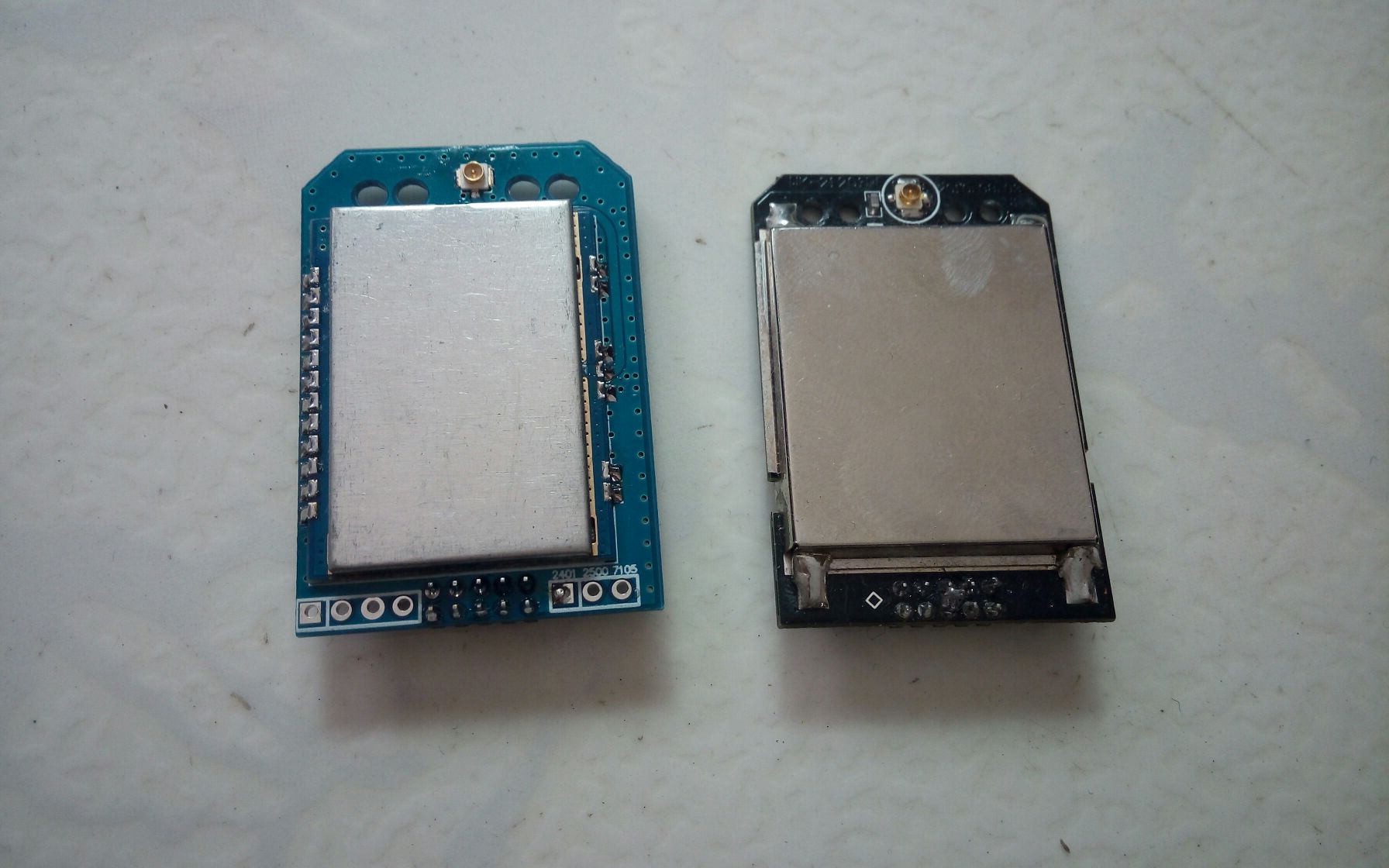
Attached is new 4in1 module for Deviation/DEVO , 4in1 board is attached to new designed adapter board, but it's not release yet.
A7105/NRF24L01 telemetry issue(PA/LNA connection) should be sorted at this version.
EDIT : All informatiom & picture from TaoBao seller.
Please Log in or Create an account to join the conversation.
- victzh
-
- Offline
- Posts: 1386
Please Log in or Create an account to join the conversation.
- dc59
-
Topic Author
- Offline
- Posts: 799
victzh wrote: Old module should not have a problem with nRF, only with A7105 - it does not have any connection to PA/LNA enable. nRF is connected and should work both with telemetry and auto acknowledge.
Thanks for clarify.
Please Log in or Create an account to join the conversation.
- blackmoon
-
- Offline
- Posts: 402
The thing is does this works without code modification ?
Lets not forget that the 7e is already at his limit, and coders seem not to like coding new stuff for it. How will code modification for 6s/8/10.. translate to 7E and which chunks will have to disappear from the actual 7E code for it to fit ? That's the big question...
You do not actually need to route SCK, MOSI and MISO over tiny. These got directly from main mcu to 4in1.
Wouldn't timing issues arise from such a configuration?
Anyway it's irrelevant t now that a drop in 4-1 is available.
Please Log in or Create an account to join the conversation.
- BirdBarber
-
- Offline
- Hummingbird Assassin
- Posts: 134
dc59 wrote: @midelic
Attached is new 4in1 module for Deviation/DEVO , 4in1 board is attached to new designed adapter board, but it's not release yet.
.
I love it! It's the design I was hoping somebody would make back in post 46440.
Please Log in or Create an account to join the conversation.
-
Home

-
Forum

-
Development

-
Development

- Devo 12s 3in1 / 4in1 RF module neat installation.


