
- Posts: 138
7e/Ultimate7e, adding the devo version 4in1
- Gerhard_H
-
- Offline
Less
More
25 Jan 2017 23:00 #58393
by Gerhard_H
Replied by Gerhard_H on topic 7e/Ultimate7e, adding the devo version 4in1
Yes, THX, have had the (old) protocol list from my other Devo7e in the memory.
Copied the right one but instead of Mismatch Error I now only have Walkera, Devo, J6 and DSMX available . . .
That's the Hardware.ini
has_pa-cyrf6936 = 1
enable-a7105 = A13
has_pa-a7105 = 1
enable-cc2500 = A14
has_pa-cc2500 = 1
enable-nrf24l01 = A15
has_pa-nrf24l01 = 1
Tried to swap A13 and A15 but no success
Not my day . . .
- HappyHarry
-
Topic Author
- Offline
Less
More
- Posts: 1136
25 Jan 2017 23:18 #58395
by HappyHarry
Replied by HappyHarry on topic 7e/Ultimate7e, adding the devo version 4in1
how do you mean the rest of the protocols are not availble? have you checked your wiring for shorts, and good continuity? is the 4in1 getting 5V? remember it doesn't use pins 10 and 11 for power as they are only 3.3V, you need to use pins 6 and 7, can you show some pics of your wiring?
- Gerhard_H
-
- Offline
Less
More
- Posts: 138
26 Jan 2017 14:56 #58408
by Gerhard_H
Replied by Gerhard_H on topic 7e/Ultimate7e, adding the devo version 4in1
- The unavailable protocols are these which begin with a "star".
- I do have 5 Volts for the 4in1 (5,25V)
- MCU pin 50
How can I check for short with neighbour-pins? May I simply take the Ohm-Meter? Don't want to burn the chip ( or maybe some hyper sensitive stuff within)....
- Checked pin 50 with a pocket oszilloscope - there's a signal which nearly instantly (or very fast) disappears after connecting the scope; maybe the oszi-load is too high, no idea.....
Next I'll do is to go through the complete wiring, maybe some wire is broken ...
- Gerhard_H
-
- Offline
Less
More
- Posts: 138
26 Jan 2017 15:10 #58410
by Gerhard_H
Replied by Gerhard_H on topic 7e/Ultimate7e, adding the devo version 4in1
Last post is from half a day ago - just forgotten to submit . . .
Update:
Got to make a break . . . .
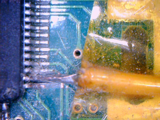
There had been shorts around pin 50. Tried to fix by scratching the bridges away, seemed it had worked,
Also had found pin 9 on the module loose, resoldered.
Could have been shorts at pin 1 also (some loose strand), fixed.
But : Now there are 3,6 Volts at 6/7 . . . .
Attach 2 Pics showing situation around pin 50.
But now I
 definitely make a break . . .
Update:
Got to make a break . . . .
There had been shorts around pin 50. Tried to fix by scratching the bridges away, seemed it had worked,
Also had found pin 9 on the module loose, resoldered.
Could have been shorts at pin 1 also (some loose strand), fixed.
But : Now there are 3,6 Volts at 6/7 . . . .
Attach 2 Pics showing situation around pin 50.
But now I
- Gerhard_H
-
- Offline
Less
More
- Posts: 138
26 Jan 2017 18:30 #58416
by Gerhard_H
Replied by Gerhard_H on topic 7e/Ultimate7e, adding the devo version 4in1
Since there still was no 5V at 6/7 I followed
www.deviationtx.com/forum/how-to/5955-7e...-4in1?start=40#54542
This gave me more Volts depending on which battery used - 4 NiMh (not full loaded) around 4,8 Volts, 4 Batteries AA brought 5,3 Volts at the module.
Switching on the radio now there's no further message saying some module is missing.
But again I can't use to some protocols (Asterisk followed by the name of the protocol).
Protocols like DSMX or WK or DEVO seem to work, but next I'll check it out wether they're really working.
- HappyHarry
-
- Offline
Less
More
- Posts: 1136
27 Jan 2017 19:43 #58448
by HappyHarry
Replied by HappyHarry on topic 7e/Ultimate7e, adding the devo version 4in1
the voltage will be variable as it is battery voltage then dropped through a diode, but the 4in1 has an ldo onboard so as long as it gets >~3.7v it will be fine.
the fact that there's an asterisk is likely a hardware.ini problem, what program are you using to edit the file? the best choice is notepad++ >> notepad-plus-plus.org/ as the built in windows editors cause issues.
try using this below
but be sure that the A13/14/15 are aimed at the correct rf chips, A13=TMS, A14=TCK, A15=MCU Pin50
the fact that there's an asterisk is likely a hardware.ini problem, what program are you using to edit the file? the best choice is notepad++ >> notepad-plus-plus.org/ as the built in windows editors cause issues.
try using this below
;Only useful for transmitters with an after-market vibration motor
;enable-haptic=1
;
;switch_types: 3x4, 3x3, 3x2, 3x1, 2x8, 2x7, 2x6, 2x5, 2x4, 2x3, 2x2, 2x1, potx2, potx1
;May occur more than once if necessary.
;Add nostock if stock FMOD and HOLD switches have been removed.
; extra-switches = nostock
; extra-switches = 3x4
; extra-switches = 2x2
; extra-switches = potx2
;
;button_types: trim-all, trim-(left|right)-(up|down|both)
;May occur more than once if necessary.
;extra-buttons=
;
[modules]
; there is no need to enable the cyrf6936 module unless
; it is wired to an alternate port. It is Enabled automatically otherwise
; enable-cyrf6936 = B12
has_pa-cyrf6936 = 1
enable-a7105    = A13
has_pa-a7105    = 1
enable-cc2500   = A14
has_pa-cc2500   = 1
enable-nrf24l01 = A15
has_pa-nrf24l01 = 1
; enable-multimod = A13
but be sure that the A13/14/15 are aimed at the correct rf chips, A13=TMS, A14=TCK, A15=MCU Pin50
- Gerhard_H
-
- Offline
Less
More
- Posts: 138
27 Jan 2017 22:03 #58453
by Gerhard_H
Replied by Gerhard_H on topic 7e/Ultimate7e, adding the devo version 4in1
THX a lot !
I do use notepad++ since I go with Deviation.
But last times I just copied the inis direct from the computer with Windows Notepad.
Now I copied your ini via notepad++ - amazing . . .
I now have S-FHSS for instance.
But when I switched on the radio the "Missing Modules! A7105" message did pop up again.
And I have these protocols with leading Asterisk :
*Joysway
*Hubsan4
*AFHDS-2A
*Flysky
This is the port which comes from mcu pin50.
I now consider to forget these protocols, I don't really need them and I avoid the risk to damage the mcu.
. . . .
OK, disabled A7105 . . .
- HappyHarry
-
- Offline
Less
More
- Posts: 1136
27 Jan 2017 22:19 #58454
by HappyHarry
Replied by HappyHarry on topic 7e/Ultimate7e, adding the devo version 4in1
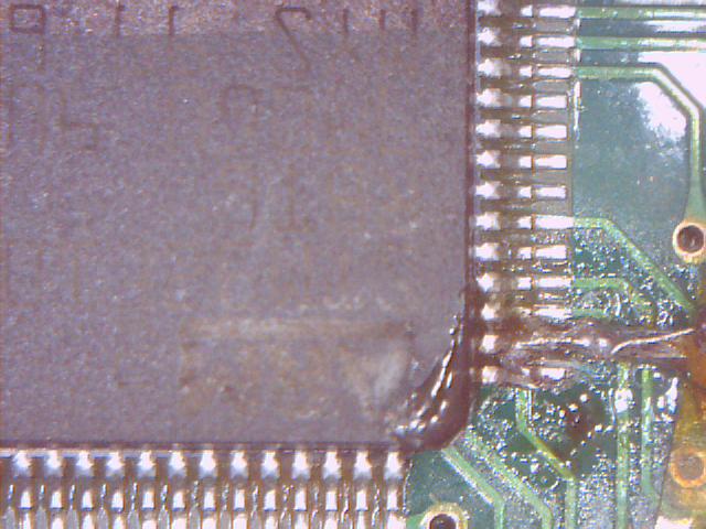
that's kinda good news ") , i think looking at your pictures the wire from pin50 might be shorting against the traces from pins 51 and 52, it looks as if when scraping to remove the shorts between mcu pins you removed some of the solder mask over those traces allowing the wire to short there. for future reference for others attempting this mod imo the best option for soldering wires to the mcu is to have them approach from the mcu side like this
, i think looking at your pictures the wire from pin50 might be shorting against the traces from pins 51 and 52, it looks as if when scraping to remove the shorts between mcu pins you removed some of the solder mask over those traces allowing the wire to short there. for future reference for others attempting this mod imo the best option for soldering wires to the mcu is to have them approach from the mcu side like this

and fixing them in place with hot glue. i would be sure to check if those traces from the pins are shorting as pins 51 and 52 are for the fmode and hold switch, you wouldn't want them triggering by mistake during flight, you could adjust the wire as i've shown above, though if you are happy to avoid using the a7105 based protocols (i understand not wanting to risk any more problems) and if they are shorting i'd just remove that wire altogether.
and fixing them in place with hot glue. i would be sure to check if those traces from the pins are shorting as pins 51 and 52 are for the fmode and hold switch, you wouldn't want them triggering by mistake during flight, you could adjust the wire as i've shown above, though if you are happy to avoid using the a7105 based protocols (i understand not wanting to risk any more problems) and if they are shorting i'd just remove that wire altogether.
- Gerhard_H
-
- Offline
Less
More
- Posts: 138
28 Jan 2017 15:47 #58474
by Gerhard_H
Replied by Gerhard_H on topic 7e/Ultimate7e, adding the devo version 4in1
I'm out for a while . . . 
Have to wait for a new 7e (takes a lot of time from BG)
OK . . .
Removed the loose wire end from pin 50 . . .
Wire hadn't been loose - I removed the wire with the pin on it . . .
Well, let's proceed without A7105.
But when I turned on the radio I found that 24101 also was gone . . .
This was the 1st radio loss . . .
I had a spare radio which lacked with range issues. Let's take this.
First I had to remove (again) the tx module. Though the procedure wasn't new for me, I wasn't careful enough with desoldering the 7 hookups. Lifted every da . . . single trace. No chance.
This was the 2nd radio loss . . .
Enough for today . . .
CU again next month . . .
- HappyHarry
-
- Offline
Less
More
- Posts: 1136
28 Jan 2017 17:08 #58477
by HappyHarry
Replied by HappyHarry on topic 7e/Ultimate7e, adding the devo version 4in1
sorry to hear that bud  , the second radio may still be usable though, in the centre of each pad you lifted you will see a small via remains, and you can solder to those using small gauge wire (like the kynar i use) and some care. also those pads are very easy to lift, imo the safest way to remove the module is to use chipquik, that way you don't need near as much heat and as such don't risk damaging the adhesive bond.
even when i did my first 4in1 i was really careful, i mixed in leaded solder with the original lead free, used a solder sucker to remove almost all the solder and i thought i pulled the module off without damaging them, but when i went to solder the wires for the 4in1 the pad from pin6 just lifted to the iron as soon as i touched it :/ so now i wont even attempt to do the stock module removal without chipquick
even when i did my first 4in1 i was really careful, i mixed in leaded solder with the original lead free, used a solder sucker to remove almost all the solder and i thought i pulled the module off without damaging them, but when i went to solder the wires for the 4in1 the pad from pin6 just lifted to the iron as soon as i touched it :/ so now i wont even attempt to do the stock module removal without chipquick
- Gerhard_H
-
- Offline
Less
More
- Posts: 138
29 Jan 2017 07:42 #58520
by Gerhard_H
Replied by Gerhard_H on topic 7e/Ultimate7e, adding the devo version 4in1
THX for condolences ")
Concerning your comment that not everything's lost : I assume you mean that tiny hole in the middle of where the pads had been, right ? Where I could notice kinda metallic shimmer around the hole, so I tried to apply some solder and at some points it looked like it could work. But I had been unsure.
Now I understand your comment in that way : The pads are supplied with contacts through the plate (or layer respectively) which could be used (as life saver . . .). Furthermore - if I had understood right - you put some wire into that hole ? Honestly said I have no ideas about what a gauge wire is but that doesn't matter as long as he provides connection.
As first step I had adapted one of my soldering tips to kinda blade, 0,6 mm thick. Seems to work well, especially around the mcu.
Now I can try to follow Your hints.
Here's my new soldering tip:
- eirikso
-
- Offline
Less
More
- Posts: 31
31 Jan 2017 14:55 #58591
by eirikso
Replied by eirikso on topic 7e/Ultimate7e, adding the devo version 4in1
I just installed the 4-in-one module in a brand new Devo 7e
No error messages when powering up. I have tested it on DSM2 controlling a quad and also controlling a small Eachine H8 Mini.
But when I try to bind to a FrSky D4R-II I have no success. I choose FrSky-V8, fire up the D4R with the bind button pressed -> two solid leds, hit "Bind" on the Devo, it says it is binding, but no success.
Any ideas where to start debugging?
- HappyHarry
-
- Offline
Less
More
- Posts: 1136
31 Jan 2017 16:19 #58592
by HappyHarry
Replied by HappyHarry on topic 7e/Ultimate7e, adding the devo version 4in1
adjust the freq-fine setting in the protocol options
- eirikso
-
- Offline
Less
More
- Posts: 31
31 Jan 2017 19:01 #58598
by eirikso
Replied by eirikso on topic 7e/Ultimate7e, adding the devo version 4in1
Unfortunately I don't get the extra menu for the frsky-v8-protocol. I can only adjust freq-fine for FrSky and FrSkyX. As far as I understand I should use FrSky-8 for the D4R-II?
- taksmara
-
- Offline
Less
More
- Posts: 9
03 Feb 2017 05:52 #58684
by taksmara
As you say, none available in South Africa, and chip quik will cost about $30 to bring in. So is it normal tin lead rosin core solder wire that you are reffering too?
Replied by taksmara on topic 7e/Ultimate7e, adding the devo version 4in1
victzh wrote: This way everything depends on how much solder is there when you lift the module under such large an angle. If you wicked it well before you can get away with it. If not - almost sure way to lift a pad or two. Chip Quik works reliably, one $15 pack is enough to unsolder dozens of modules (you need 2-3mm piece of it on every large blob, maybe less). The trick is to remove as much of it as possible after unsoldering - it lowers melting temperature of the solder you going to apply, so to have reliable connection you better clean it up.
If you live in a country with limited availability of low temp alloys, then use led-based solder to dilute the original led-free as @timps did.
As you say, none available in South Africa, and chip quik will cost about $30 to bring in. So is it normal tin lead rosin core solder wire that you are reffering too?
- eirikso
-
- Offline
Less
More
- Posts: 31
06 Feb 2017 23:23 #58836
by eirikso
Replied by eirikso on topic 7e/Ultimate7e, adding the devo version 4in1
Still trouble with FrSky.
Have tried with a D4R-II and a V8RN2. With FrSky and FrSky-V8. With the FrSky setting I have tried several different freq fine tuning. I have tested both receivers on my Taranis and they bind at once with that one.
As far as I understand I need to use the FrSky-V8 setting for the D4R-II. But that setting has no extra options.
So I am out of ideas. Anyone else here with ideas of what I am doing wrong?
- hexfet
-
- Offline
Less
More
- Posts: 1971
06 Feb 2017 23:49 #58838
by hexfet
Replied by hexfet on topic 7e/Ultimate7e, adding the devo version 4in1
The D4R-II uses the D8 protocol, which in deviation is plain "Frsky".
Start with the devo turned on.
Hold down bind button on D4R, apply power. LEDs stay solid red and green.
Press Bind button on deviation model setup screen. Red LED starts flashing.
Press OK on devo or wait for timeout.
Remove power from D4R. Apply power to D4R. Green LED on solid.
If no green LED, change Fine Freq setting by 10 and repeat.
- eirikso
-
- Offline
Less
More
- Posts: 31
07 Feb 2017 13:50 #58873
by eirikso
Replied by eirikso on topic 7e/Ultimate7e, adding the devo version 4in1
Thank you! Will sit down and go through this systematically when I have a bit of time.
- Maxner
-
- Offline
Less
More
- Posts: 32
08 Feb 2017 07:01 #58900
by Maxner
Replied by Maxner on topic 7e/Ultimate7e, adding the devo version 4in1
Hello,
I'm not happy with my 3in1 module. Despite the Polopu for the 3.3V supply, the connection to the Eachine E010 is unstable.
Anyway, I would now like to help and use the 4in1 module. However, I am unsure which module is up-to-date and works error-free and which wiring is correct:
This module?
And the wiring from this post?
I would like to use all 4 RF chips to control eachine E010, Hubsan X4 and some DSM2 / DSMX models. Can I use for the 2.4 GHz each WLAN antenna or do they have a recommendation (please a BG link)?
Thanks for your effort (and sorry for my "Google-English")
- timps
-
- Offline
Less
More
- Posts: 6
08 Feb 2017 07:34 #58902
by timps
Replied by timps on topic 7e/Ultimate7e, adding the devo version 4in1
2x yes to the module and wiring. The exact mapping of the pins 9, 10, 13 (extra chips/protocols) does not matter, as long as you correct it in your hardware.ini (see a few comments above).
I simply used the antenna and connector that is linked in the first post.
I simply used the antenna and connector that is linked in the first post.
Time to create page: 0.147 seconds