- Posts: 17
DM002 protocol (contains captures)
- lani
-
Topic Author
- Offline
Discussion initiated at www.deviationtx.com/forum/protocol-devel...gw008?start=80#60417 but continuing here as it seems to be different protocol than CX10 or GW008
The drone has the PAN159CY chip whereas the stock TX has XN297LBW 1615 radio.
I took the following SPI captures from the TX, stored to drive.google.com/drive/folders/0BxykaYXTxO4rNk1WT2lpaWVPREk
- "startup": After TX poweron, no actions to any of the controls, throttle at minimum
- "bind": Capture started while TX is already on and the drone waits in bind mode. During the capture the throttle is swept MIN-MAX-MIN which executes the bind.
- "right stick loop": starting the capture when drone has been bound and the right stick is in bottom left position. During capture moved the stick first up, then right, then down and again left.
- "yaw sweep": starting the capture when drone has been bound and the left stick is in bottom left position. During capture swep the stick to right bottom corner and back.
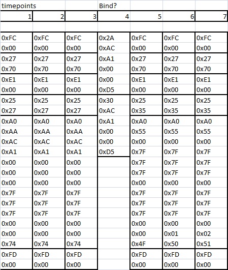
All the captures have also a csv SPI export alternative. Image attached here is what I think happens during the bind:
* When powered on, a combination of 4x2byte frames + 1x13byte frame + 1x2byte frame is sent periodically with fixed content
* Upon bind, the periodical frame is preceded by 2x6byte frames (bind command??)
* After bind, the periodical 4x2 + 1x13 + 1x2 continues but now it has different data and two sequence counters in the end
Looks any familiar? Anything more I could do? I have embedded sw background but quite fresh on the RC and radio side.
My ultimate target is to get the protocol for the multi-protocol DIY TX module github.com/pascallanger/DIY-Multiprotocol-TX-Module and use it with OpenTX. However i think this could be beneficial for deviation also and you seem to have a proper community power to crack this.
Edit: There was an error in my above bind analysis, also fixed the pic
Please Log in or Create an account to join the conversation.
- planger
-
- Offline
Same speed and config: XN297, scramble enabled, 1Mbps, no AA.
But apart from that everything is different:
- packet size is 12 bytes (and not 15)
- packet period is around 6100µs (not 8200 or 4100)
- bind is on channel 0x27
- bind address: 0x26 0xA8 0x67 0x35 0xCC
- bind packet: 0xAA 0xAC 0xA1 0x00 0x00 0x00 0x7F 0x7F 0x7F 0x00 0x00 0x74
- bind starts with 0xAA then TX ID 0xAC 0xA1 0x00 0x00
- bind ends with 0x74 which is a CRC. CRC is the sum of packet[0..10] bytes stored on packet[11].
- switch to normal TX ID is set to 0xAC 0xA1 0x00 0x00 0xD5
- normal packet idle (=no stick input): 0x55 0x00 0x7F 0x7F 0x7F 0x00 0x7F 0x7F 0x7F 0x00 0x00 0x4F
- normal packet[0]=0x55
- normal packet[2]=yaw -> center 0x7F, full left 0x57, full right 0xA7 => not sure if there is a rate mode on this quad which might increase the stick range?
- normal packet[3] and packet[4]= right stick for whatever that means... -> center 0x7F, full left 0x57, full right 0xA7 => not sure if there is a rate mode on this quad which might increase the stick range?
- normal packet[10]=frame counter: 0x00..0x02 (skip 0x03) 0x04..0x06 (skip 0x07) 0x08..0x0A (skip 0x0B) 0x0C..0x0E -> roll over
- normal packet[11]=CRC. CRC is the sum of packet[0..10] bytes stored on packet[11].
- normal channels: 3 times each 0x35 associated to frame 0x00..0x02, 0x39 associated to frame 0x04..0x06, 0x3B associated to frame 0x08..0x0A, 0x3D associated to frame 0x0C..0x0E
That's all from the logs.
Pascal
Please Log in or Create an account to join the conversation.
- goebish
-
- Offline
- NRF Weirdo
- Posts: 2633
Please Log in or Create an account to join the conversation.
- planger
-
- Offline
- like Yaw sweep L to R on all stick inputs (Throttle, Aileron, Elevator, Rudder)
- need a dump of the special features like flip
After we will need more dumps from different TXs to establish the relation between TX ID and RF channels (if any).
Pascal
Please Log in or Create an account to join the conversation.
- goebish
-
- Offline
- NRF Weirdo
- Posts: 2633
Please Log in or Create an account to join the conversation.
- lani
-
Topic Author
- Offline
- Posts: 17
Please Log in or Create an account to join the conversation.
- lani
-
Topic Author
- Offline
- Posts: 17
planger:
* Why do you say packet size is 12 as the SPI packet is 13bytes? The first SPI byte does not go in the radio package?
* Otherwise I agree with your findings
goebish/planger:
* My colleague has the identical set so we can try his TX as well for the TX id
other:
* I will try to check how the flight mode affects control ranges
* I will check what the right trigger button actually does (chinese manual is not very clear and I havent yer learnt how to use it). Headless mode and flip are mentioned in the manual.
Please Log in or Create an account to join the conversation.
- goebish
-
- Offline
- NRF Weirdo
- Posts: 2633
lani wrote: goebish/planger:
* My colleague has the identical set so we can try his TX as well for the TX id
Yes, we need several txid / rf channels combo to try to guess how it works, or worst case implement a list of known working pairs.
Please Log in or Create an account to join the conversation.
- planger
-
- Offline
You have to decode the SPI frames... 0xA0 is the XN297 instruction meaning write TX payload = sends everything I'm giving you after.planger:
* Why do you say packet size is 12 as the SPI packet is 13bytes? The first SPI byte does not go in the radio package?
* Otherwise I agree with your findings
With that table we have everything to emulate the protocol since we have sticks + features bits.
If you decode the SPI frames, you'll see that the frequency changes each time there is a jump in the sequence.Sequence counter: Loops 0..16 but skip some values
So basically it's something like this:
packet_count++;
if(packet_count&0x03)
{
    packet_count++;
    hopping_frequency_no++;
    hopping_frequency_no&=4;
    NRF24L01_WriteReg(NRF24L01_05_RF_CH, hopping_frequency[hopping_frequency_no]);
}
packet_count&=0x0F;Pascal
Please Log in or Create an account to join the conversation.
- planger
-
- Offline
For Taranis:
- Custom protocol number = 33
- sub_protocol = 0
- ch5=Flip, ch6=LED, ch7=Headless
Please report.
Pascal
Please Log in or Create an account to join the conversation.
- lani
-
Topic Author
- Offline
- Posts: 17
* Tested also leds and flip, both work just fine.
* The pitch and roll channels were mixed when creating model with OpenTX defaults.
* I needed to invert the pitch curve.
* Control gains are quite low so let's find the actual max ranges to be put in the protocol. User can tune the flight mode in the tx side according to preference if it is too "wild".
Is this protocol now hardcoded for my controller ID? What I know already about my colleagues model is that i can bind my TX with his drone and we can also bind two drones to same TX.
Once again THANK YOU, i can finally scrap the plastic TX crap..
Please Log in or Create an account to join the conversation.
- goebish
-
- Offline
- NRF Weirdo
- Posts: 2633
Please Log in or Create an account to join the conversation.
- planger
-
- Offline
My bad, I've inverted both channels it in the code... I've written it thinking I need to check later and forgot...* The pitch and roll channels were mixed when creating model with OpenTX defaults.
I've also fixed pitch being reversed.
New version on github contains the fixes.
In the DM002_nrf24l01.ino source file, you can change these lines:Control gains are quite low so let's find the actual max ranges to be put in the protocol.
packet[2] = convert_channel_8b_scale(RUDDER,0x57,0xA7);
packet[3] = convert_channel_8b_scale(AILERON, 0x57,0xA7);
packet[4] = convert_channel_8b_scale(ELEVATOR, 0xA7,0x57);Yes it is.Is this protocol now hardcoded for my controller ID?
Can you try to change the values AC and A1 in the lines below to see if it still works or not?
memcpy(rx_tx_addr,(uint8_t *)"\xAC\xA1\x00\x00\xD5",5);Pascal
Please Log in or Create an account to join the conversation.
- planger
-
- Offline
It should be the same on the original TX, can you confirm?Control gains are quite low so let's find the actual max ranges to be put in the protocol.
If modifying the end points as proposed earlier does not give anything, there is still something to try out.
I'm thinking, might be wrong and you need to test, that the second part of the payload with the 0x7F are in fact the trims. So we could move the trims at the same time as moving the main channels to increase the range which is done on some models.
Pascal
Please Log in or Create an account to join the conversation.
- SeByDocKy
-
- Offline
- Posts: 1016
goebish wrote: I'll ask SebyDocky to post a capture of his Tx as well.
I tried but I was not able to solder probes .... on the chips pads
Please Log in or Create an account to join the conversation.
- lani
-
Topic Author
- Offline
- Posts: 17
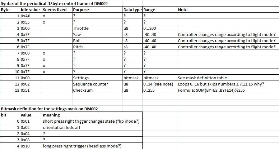
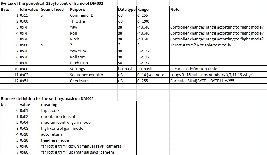
* The control ranges -40..40 were true also in the "gain modes" 2 and 3 which bring more sensitivity to the Yaw,Pitch,Roll channels
* New bitmask entries found for the "gain modes". For the protocol, should we hardcode a mode or let the user select it? The control range is so small that maybe hardcoding the gain 3 will lose resolution if user wants to calm down the drone by restricting the range in his TX.
* Headless mode was not the right trigger button, instead it activates by pressing the right stick (fixed to the bitmask). Right trigger longpress was instead some kind of auto return mode.
* The trims were truly carried as separate values in the frame. Other channels than throttle had them.
* "throttle trim switch" on the TX controls two bits in the mask. The manual says this switch is for "camera" but cannot see any other effect than making the drone leds blink in case one of these bits are up.
Updated spec attached. Will post again as soon as we get the TX id ripped from the other TX and maybe some other tests.
Please Log in or Create an account to join the conversation.
- lani
-
Topic Author
- Offline
- Posts: 17
TXID from the colleague's TX: (0x47 0x93)
Otherwise bind frame stays the same.
Would this pretty much imply it is just a random number? Should I just try few options and additionally the special cases 0x00 0x00 and 0xFF 0xFF?
Please Log in or Create an account to join the conversation.
- goebish
-
- Offline
- NRF Weirdo
- Posts: 2633
Please Log in or Create an account to join the conversation.
- lani
-
Topic Author
- Offline
- Posts: 17
Package number for bind frame: 1465
Please Log in or Create an account to join the conversation.
- goebish
-
- Offline
- NRF Weirdo
- Posts: 2633
id: AC A1
rf: 35 39 3b 3d
Other TX:
id: 47 93
rf: 34 39 43 48
That's hard to guess the relationship with only 2 sets ... I usually consider 3 is a minimum.
Please Log in or Create an account to join the conversation.
-
Home

-
Forum

-
Development

-
Protocol Development

- DM002 protocol (contains captures)


