
- Posts: 88
MultiModule help
- skretchmer
-
Topic Author
- Offline
Less
More
07 Aug 2015 23:31 #36661
by skretchmer
Replied by skretchmer on topic MultiModule help
i looked up that error, it was from old firmware. I upgraded the firmware on my programmer and I do not get the error anymore, however, the modules still do not work. the TX still does not see them.
C:\Users\sam\Desktop>avrdude -F -p t24 -c usbasp -e -U flash:w:avr.hex
avrdude: AVR device initialized and ready to accept instructions
Reading | ################################################## | 100% 0.05s
avrdude: Device signature = 0x1e910b
avrdude: erasing chip
avrdude: reading input file "avr.hex"
avrdude: input file avr.hex auto detected as Intel Hex
avrdude: writing flash (338 bytes):
Writing | ################################################## | 100% 0.23s
avrdude: 338 bytes of flash written
avrdude: verifying flash memory against avr.hex:
avrdude: load data flash data from input file avr.hex:
avrdude: input file avr.hex auto detected as Intel Hex
avrdude: input file avr.hex contains 338 bytes
avrdude: reading on-chip flash data:
Reading | ################################################## | 100% 0.12s
avrdude: verifying ...
avrdude: 338 bytes of flash verified
avrdude: safemode: Fuses OK
avrdude done. Thank you.
C:\Users\sam\Desktop>avrdude -p t24 -c usbasp -U lfuse:w:0xe2:m -U hfuse:w:0xdf:
m -U efuse:w:0xff:m
avrdude: AVR device initialized and ready to accept instructions
Reading | ################################################## | 100% 0.06s
avrdude: Device signature = 0x1e910b
avrdude: reading input file "0xe2"
avrdude: writing lfuse (1 bytes):
Writing | ################################################## | 100% 0.02s
avrdude: 1 bytes of lfuse written
avrdude: verifying lfuse memory against 0xe2:
avrdude: load data lfuse data from input file 0xe2:
avrdude: input file 0xe2 contains 1 bytes
avrdude: reading on-chip lfuse data:
Reading | ################################################## | 100% 0.02s
avrdude: verifying ...
avrdude: 1 bytes of lfuse verified
avrdude: reading input file "0xdf"
avrdude: writing hfuse (1 bytes):
Writing | ################################################## | 100% 0.02s
avrdude: 1 bytes of hfuse written
avrdude: verifying hfuse memory against 0xdf:
avrdude: load data hfuse data from input file 0xdf:
avrdude: input file 0xdf contains 1 bytes
avrdude: reading on-chip hfuse data:
Reading | ################################################## | 100% 0.03s
avrdude: verifying ...
avrdude: 1 bytes of hfuse verified
avrdude: reading input file "0xff"
avrdude: writing efuse (1 bytes):
Writing | ################################################## | 100% 0.02s
avrdude: 1 bytes of efuse written
avrdude: verifying efuse memory against 0xff:
avrdude: load data efuse data from input file 0xff:
avrdude: input file 0xff contains 1 bytes
avrdude: reading on-chip efuse data:
Reading | ################################################## | 100% 0.02s
avrdude: verifying ...
avrdude: 1 bytes of efuse verified
avrdude: safemode: Fuses OK
avrdude done. Thank you.
- RedSleds
-
- Offline
Less
More
- Posts: 226
08 Aug 2015 00:18 - 08 Aug 2015 00:19 #36662
by RedSleds
DEVO 10 - Multi-module with nRF24L01 +PA +LNA, A7105 +PA, & CC2500 +PA +LNA transceivers.
Nightly Build: v4.0.1-548bbf5 (6/9/2015)
Replied by RedSleds on topic MultiModule help
...and the hardware.ini of the Tx drive looks something like this:
**************************
;Only useful for transmitters with an after-market vibration motor
;enable-haptic=1
;
;switch_types: 3x2, 3x1, 2x2
;extra-switches=
;
[modules]
; there is no need to enable the cyrf6936 module unless
; it is wired to an alternate port. It is Enabled automatically otherwise
; enable-cyrf6936 = B12
; has_pa-cyrf6936 = 1
enable-a7105 = S1
has_pa-a7105 = 1
enable-cc2500 = S3
has_pa-cc2500 = 1
enable-nrf24l01 = S402
has_pa-nrf24l01 = 1
enable-multimod = A13
**************************
Maybe try "A14", in the enable-multimod = line. in case you wired it to the TCK pin instead of the TMS pin???
Man, I am totally out of ideas if that doesn't work, and you are absolutely positive that everything is wired up correctly. If so, either the Tx was faulty right out of the box somehow, or your main board processor got ESD zapped when you were working on it. Nothing else seems to make sense.
**************************
;Only useful for transmitters with an after-market vibration motor
;enable-haptic=1
;
;switch_types: 3x2, 3x1, 2x2
;extra-switches=
;
[modules]
; there is no need to enable the cyrf6936 module unless
; it is wired to an alternate port. It is Enabled automatically otherwise
; enable-cyrf6936 = B12
; has_pa-cyrf6936 = 1
enable-a7105 = S1
has_pa-a7105 = 1
enable-cc2500 = S3
has_pa-cc2500 = 1
enable-nrf24l01 = S402
has_pa-nrf24l01 = 1
enable-multimod = A13
**************************
Maybe try "A14", in the enable-multimod = line. in case you wired it to the TCK pin instead of the TMS pin???
Man, I am totally out of ideas if that doesn't work, and you are absolutely positive that everything is wired up correctly. If so, either the Tx was faulty right out of the box somehow, or your main board processor got ESD zapped when you were working on it. Nothing else seems to make sense.
DEVO 10 - Multi-module with nRF24L01 +PA +LNA, A7105 +PA, & CC2500 +PA +LNA transceivers.
Nightly Build: v4.0.1-548bbf5 (6/9/2015)
Last edit: 08 Aug 2015 00:19 by RedSleds.
- skretchmer
-
- Offline
Less
More
- Posts: 88
08 Aug 2015 01:02 #36663
by skretchmer
Replied by skretchmer on topic MultiModule help
at this point i'm using just the multi-module board with the ATTiny chip installed. no additional modules, as was suggested earlier as a troubleshooting step. Only the enable-multimod line is uncommented in my hardware.ini. I have tried both A13 and A14, and soldering to both TCK and TMS on the TX.
I have used a multi-meter to continuity test the modules I have built, both with modules and bare boards, all the way to the TX from the ATTTiny chip itself. If I install the board with chip alone and leave the enable-multimod line commented out, the radio shows the built-in stock module as missing, but with the multi-module removed, the TX works fine with the built-in module. So the chip is doing something to the TX, it's just not identifying itself as a multi-module.
I get correct output from the programming steps. I have had one ATTTiny chip that would not program, gave errors on the command line, but the rest I have done all showed the correct output, so I am sure I am getting the chip programmed.
I have removed the modules from the two completed boards I built, and can connect any of them directly to the TX and fly an appropriate heli with the TX, so i'm not burning out things with bad soldering, and I can follow the pinouts will enough to put them in the TX.
if there was something wrong with the TX, then I would not be able to take the modules, soldered directly to the TX, and use the TX to fly DSMX, HiSky and powerstar helis.
is there anyone on here who has recently built, programmed and installed a multi-module in a 7e, or are we all just assuming this should work based on the video of someone doing it years ago on a Devo 10?
- mwm
-
- Offline
08 Aug 2015 01:15 #36664
by mwm
Could be, but might not be. I get it pretty much every time I use my usbasp, and with one exception things have worked fine afterwards, including flashing an MM.
The one exception is the last time I flashed the MM. Possibly the avrdude software updated and no longer works correctly with that warning? Not clear, as the MM had started having problems before then as well, so possibly a change in the deviation side makes this case no longer work? Having finally opened up my 6s and installed a pair of modules in it, I'm happy with 2 modules in my 10, so didn't pursue this any further.
Do not ask me questions via PM. Ask in the forums, where I'll answer if I can.
My remotely piloted vehicle ("drone") is a yacht.
Replied by mwm on topic MultiModule help
RedSleds wrote:
skretchmer wrote: "avrdude: warning: cannot set sck period. please check for usbasp firmware update".
Isn't this an error in the flashing of the micro-controller?
I still don't think it is flashed correctly. Something is wrong.
Could be, but might not be. I get it pretty much every time I use my usbasp, and with one exception things have worked fine afterwards, including flashing an MM.
The one exception is the last time I flashed the MM. Possibly the avrdude software updated and no longer works correctly with that warning? Not clear, as the MM had started having problems before then as well, so possibly a change in the deviation side makes this case no longer work? Having finally opened up my 6s and installed a pair of modules in it, I'm happy with 2 modules in my 10, so didn't pursue this any further.
Do not ask me questions via PM. Ask in the forums, where I'll answer if I can.
My remotely piloted vehicle ("drone") is a yacht.
- mwm
-
- Offline
08 Aug 2015 01:20 #36665
by mwm
That's a sign that something is broken in your hardware setup. Did you do a test for shorts between the various pins after the install?
I'm not sure anyone has ever done it on a 7e - the MM with all modules installed doesn't seem likely to fit. There was a thread recently about someone who patched it together with the modules installed via cables instead of plugged in so it could be distributed around. Not clear what else they've done, but it wouldn't surprise me if the MM didn't work on a 7e with stock firmware on both, as the 7e uses a different, much less capable microprocessor, and a different CYRF module.
Do not ask me questions via PM. Ask in the forums, where I'll answer if I can.
My remotely piloted vehicle ("drone") is a yacht.
Replied by mwm on topic MultiModule help
skretchmer wrote: If I install the board with chip alone and leave the enable-multimod line commented out, the radio shows the built-in stock module as missing,
That's a sign that something is broken in your hardware setup. Did you do a test for shorts between the various pins after the install?
is there anyone on here who has recently built, programmed and installed a multi-module in a 7e, or are we all just assuming this should work based on the video of someone doing it years ago on a Devo 10?
I'm not sure anyone has ever done it on a 7e - the MM with all modules installed doesn't seem likely to fit. There was a thread recently about someone who patched it together with the modules installed via cables instead of plugged in so it could be distributed around. Not clear what else they've done, but it wouldn't surprise me if the MM didn't work on a 7e with stock firmware on both, as the 7e uses a different, much less capable microprocessor, and a different CYRF module.
Do not ask me questions via PM. Ask in the forums, where I'll answer if I can.
My remotely piloted vehicle ("drone") is a yacht.
- skretchmer
-
- Offline
Less
More
- Posts: 88
08 Aug 2015 01:42 #36667
by skretchmer
Replied by skretchmer on topic MultiModule help
when you say sign of something broken, what can be broken? I have tested continuity to the TX from the chip, and all the pins are fine. The only thing on the board is the ATTiny chip, and wires for the connections to the TX. I have followed the diagrams on the site, and gone over it enough times to be 100% sure i have it wired correctly.
I am NOT getting the errors about sck when I program now, I upgraded the firmware on my programmer as per this site: blog.lincomatic.com/?p=1480 where it was said that the error was due to old firmware. I posted the output above from my last programming attempt, with the updated firmware programmer, which shows no errors during programming both the chip and the fuses.
I have found that if you take out the goofy backboard that the tiny speaker mounts to in the 7e there is plenty of space at the top of the TX to fit a fully assembled multimodule with the modules directly on the board. I also made a build where the modules were wired to the board with wires where they could be mounted separate from the board, but found that to be harder to fit than the board with the modules directly on the board.
I am not using stock firmware, I have now tired both 4.0.1-c3007aa and 4.0.1-ef0d76d nightly builds.
I also have 2 x 3 way additional switches installed, both of which work just fine.
- skretchmer
-
- Offline
Less
More
- Posts: 88
08 Aug 2015 03:00 #36672
by skretchmer
Replied by skretchmer on topic MultiModule help
here is my latest attempt to get any of this to work. The board in the photo has never had any modules soldered to it, and the ATTiny chip is in a socket (yes, there are empty pin holes in the socket, i only had a 18 pin socket, the 4 extra pins are folded under the socket and do not make contact with anything. If I connect the board alone, with no ATTiny chip and comment out the enable-multimodule line, the TX powers up and works fine for the CYRF module. If I insert any of the ATTiny chips that show as having been programmed successfully, it boots up and shows module missing multi-module. (when the hardware.ini file has the enable-multimodule line not commented out.)
For all I have said, I tend to think the chip is not getting programmed correctly, as the TX will not recognize the board when a chip has been installed, but has no problems with a bare board with no modules or chip.
For all I have said, I tend to think the chip is not getting programmed correctly, as the TX will not recognize the board when a chip has been installed, but has no problems with a bare board with no modules or chip.
- skretchmer
-
- Offline
Less
More
- Posts: 88
- turpo
-
- Offline
Less
More
- Posts: 6
16 Aug 2015 14:17 #36945
by turpo
Replied by turpo on topic MultiModule help
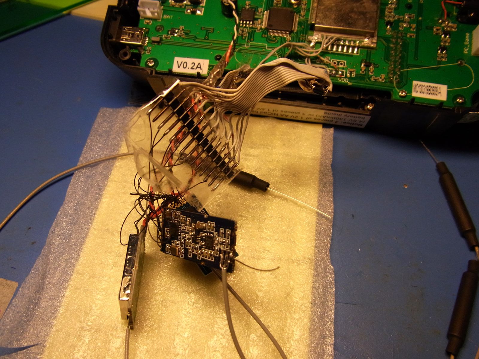
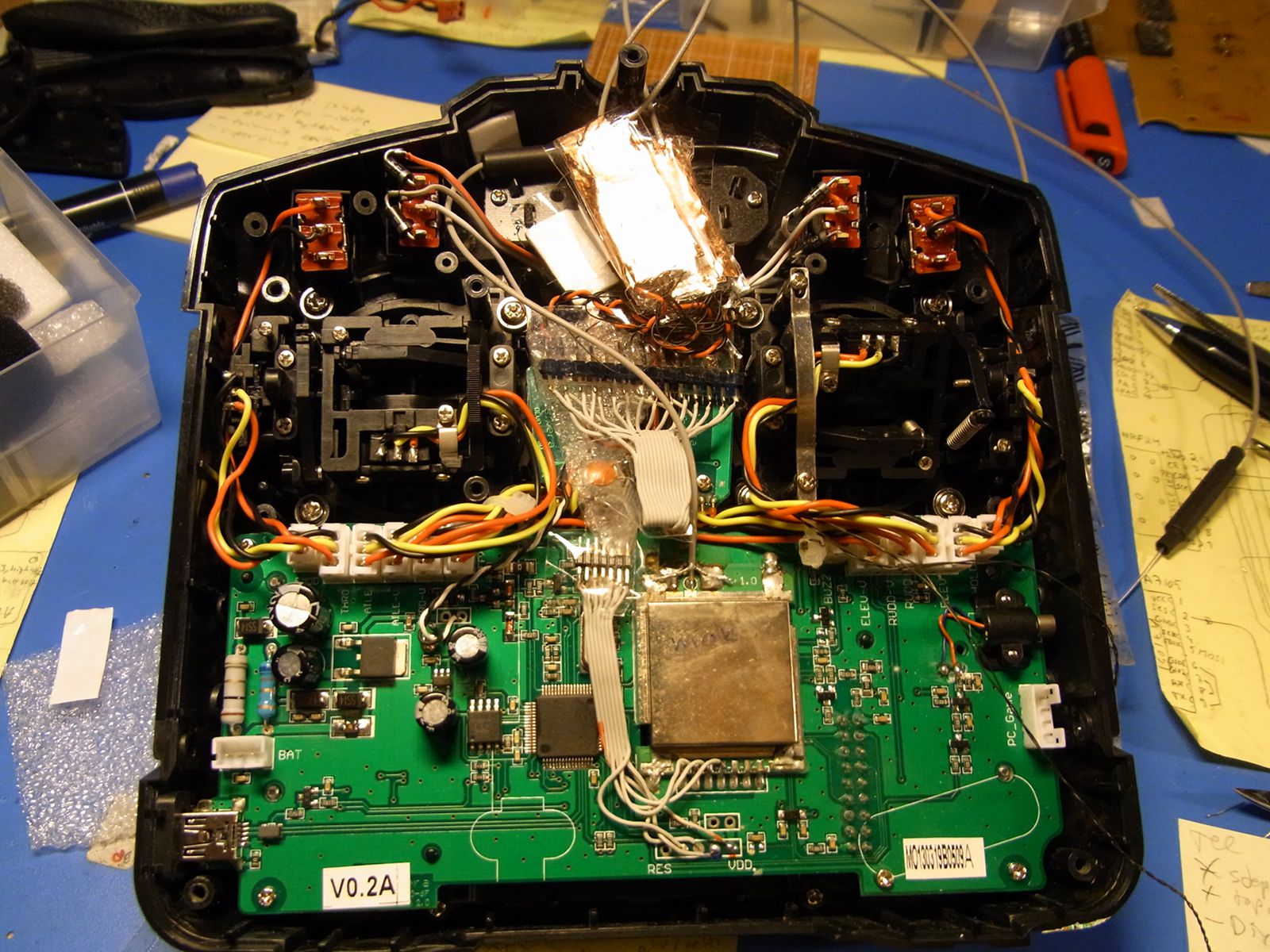
Hi skretchmer, here is photos of my MM build. I noticed the cc2500 is very low power like PA always off, so something is not right... (have to check connections first)
Other modules been working ok also cyrf.
Have you tried option "force = 1" in hardware.ini
Set the fuses corrctly ? bitbucket.org/PhracturedBlue/deviation/w...ing_the_Multi-Module : lfuse:w:0xe2:m -U hfuse:w:0xdf:m -U efuse:w:0xff:m
My hardware.ini :
;Only useful for transmitters with an after-market vibration motor
;enable-haptic=1
;
;switch_types: 3x2, 3x1, 2x2
extra-switches=3x2
;
[modules]
; there is no need to enable the cyrf6936 module unless
; it is wired to an alternate port. It is Enabled automatically otherwise
; enable-cyrf6936 = B12
has_pa-cyrf6936 = 1
enable-a7105 = s1
has_pa-a7105 = 1
enable-cc2500 = s3
has_pa-cc2500 = 1
enable-nrf24l01 = s402
has_pa-nrf24l01 = 1
enable-multimod = A13
;force = 1
- skretchmer
-
- Offline
Less
More
- Posts: 88
17 Aug 2015 01:12 #36957
by skretchmer
Replied by skretchmer on topic MultiModule help
Am I safe to assume the mosi, miso, and CSK from the modules are all also connected to the respective pins on the CYRF module? (so the only pin you "shuttle" through the ATTiny chip is the CSN pin?)
Is there a need for the CE pin on the NRF module to go to the ATTiny chip, or can it just get shorted to VCC at the module as the wiki shows? i might try wiring it up without the board itself and see if i get any different result.
i have not tried the "force", i did not see any reference to it.
i will try again with the force and let you know.
Thanks!
- skretchmer
-
- Offline
Less
More
- Posts: 88
17 Aug 2015 01:15 #36958
by skretchmer
Replied by skretchmer on topic MultiModule help
i did indeed set the fuses as per that link:
C:\Users\sam\Desktop>avrdude -p t24 -c usbasp -U lfuse:w:0xe2:m -U hfuse:w:0xdf:
m -U efuse:w:0xff:m
avrdude: AVR device initialized and ready to accept instructions
Reading | ################################################## | 100% 0.06s
avrdude: Device signature = 0x1e910b
avrdude: reading input file "0xe2"
avrdude: writing lfuse (1 bytes):
Writing | ################################################## | 100% 0.02s
avrdude: 1 bytes of lfuse written
avrdude: verifying lfuse memory against 0xe2:
avrdude: load data lfuse data from input file 0xe2:
avrdude: input file 0xe2 contains 1 bytes
avrdude: reading on-chip lfuse data:
Reading | ################################################## | 100% 0.02s
avrdude: verifying ...
avrdude: 1 bytes of lfuse verified
avrdude: reading input file "0xdf"
avrdude: writing hfuse (1 bytes):
Writing | ################################################## | 100% 0.02s
avrdude: 1 bytes of hfuse written
avrdude: verifying hfuse memory against 0xdf:
avrdude: load data hfuse data from input file 0xdf:
avrdude: input file 0xdf contains 1 bytes
avrdude: reading on-chip hfuse data:
Reading | ################################################## | 100% 0.03s
avrdude: verifying ...
avrdude: 1 bytes of hfuse verified
avrdude: reading input file "0xff"
avrdude: writing efuse (1 bytes):
Writing | ################################################## | 100% 0.02s
avrdude: 1 bytes of efuse written
avrdude: verifying efuse memory against 0xff:
avrdude: load data efuse data from input file 0xff:
avrdude: input file 0xff contains 1 bytes
avrdude: reading on-chip efuse data:
Reading | ################################################## | 100% 0.02s
avrdude: verifying ...
avrdude: 1 bytes of efuse verified
avrdude: safemode: Fuses OK
avrdude done. Thank you.
- turpo
-
- Offline
Less
More
- Posts: 6
17 Aug 2015 11:04 #36971
by turpo
Replied by turpo on topic MultiModule help
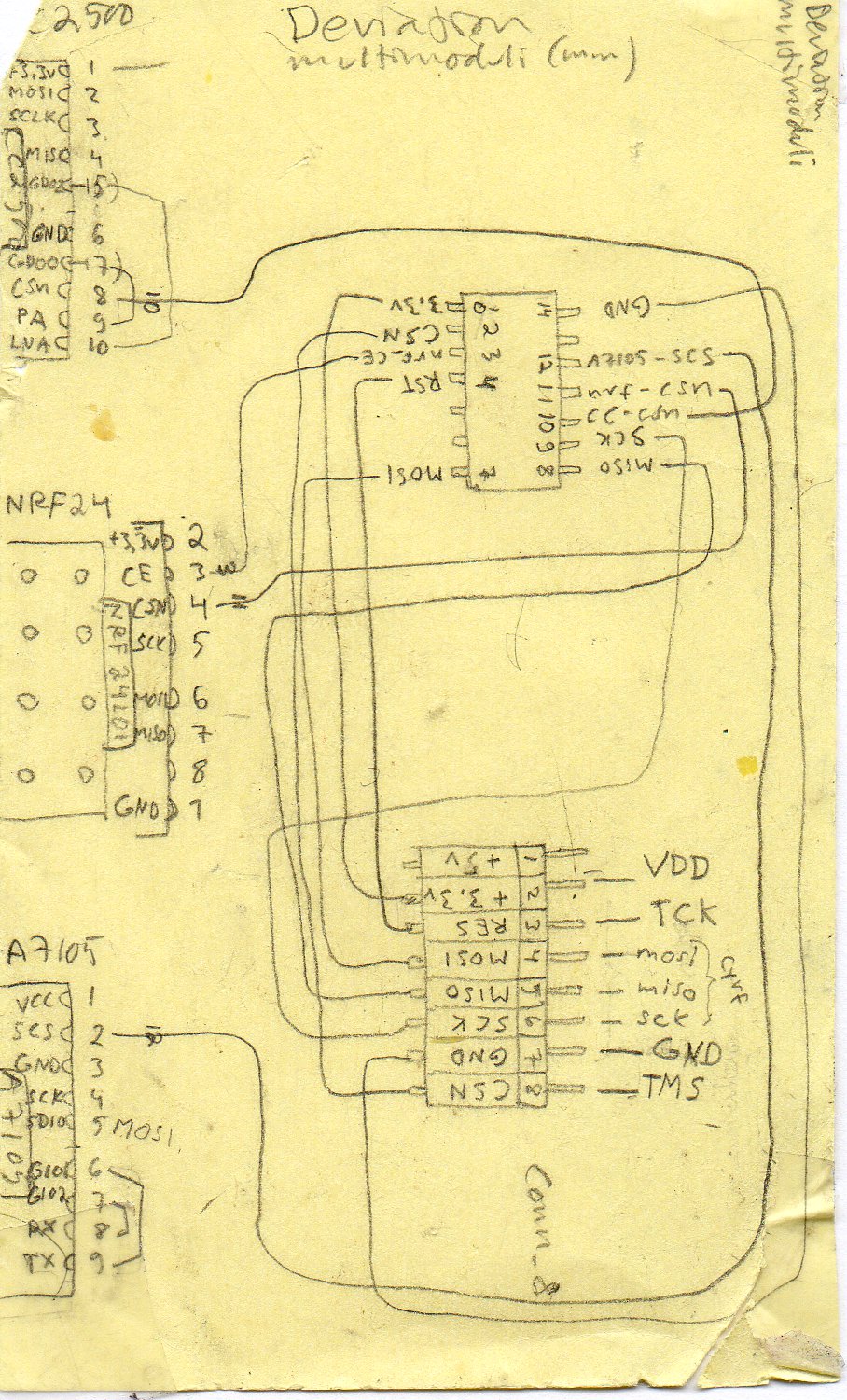
I'm not sure about the NRF CE pin usage. The MISO MOSI and SCK of modules connect to both ATTiny and devo7e-cyrf, via the smaller 8p ribbon cable (sorry the connections not show on schematics , I was lazy).
I try to help with the first photo:
The big 14 pin header correspond to ATTiny 14 pins
From left (or top) they are:
14. GND , shared with all modules, only signal ground
13. not connected
These are connected to modules (thin black wires):
12. A7105 chip select
11. nrf2401 chip select
10. cc2500 chip select
These 3 are each connected to each module (shared wires):
9. SCK
8. MISO
7. MOSI
6. nc
5. nc
4. reset
3. nrf2401 CE , this is connected to nrf module
2. CSN
1. 3.3v , not leading to modules as I power them separate (via a thick black and white wire, starting from devo7e pcb, ending to a 662k 3.3v regulator, then LC filter, then twisted pair wire to each module, I wanted to be sure they get clean power. And power not interfering signals.)
(I also changed the diode , near the lable "BAT" on the devo7e pcb to a resettable fuse, to remove the voltage drop of diode to better use 1s lipo.)
- skretchmer
-
- Offline
Less
More
- Posts: 88
17 Aug 2015 14:35 #36980
by skretchmer
Replied by skretchmer on topic MultiModule help
ok, I tried one more time with the v1.3 multi-module board as seen in the photos here. I got it to program and fuses set (see output below). I am trying to do this with just the board. (i have sockets installed on the board for module testing when/if i ever get the board recognized. I added the "force = 1" to my hardware.ini (see below), but I still get "module missing multi-module" when I power up the TX. I have verified all the pins are connecting through from the Chip to the TX with a multi meter, and verified there is no continuity between pins from bridging anywhere. The TX works fine if I remove the chip from the board, and comment out the multi module line in the hardware.ini, even with the board installed as shown. Only after inserting the ATTiny (yes I am sure i am getting it in the correct orientation in the board), do I then get errors. With the multi-module commented out in the hardware.ini file I get CYRF module missing, with the multi=module active in the config I get the multi-module missing error.
;Only useful for transmitters with an after-market vibration motor
;enable-haptic=1
;
;switch_types: 3x2, 3x1, 2x2
extra-switches=3x2
;
[modules]
; there is no need to enable the cyrf6936 module unless
; it is wired to an alternate port. It is Enabled automatically otherwise
; enable-cyrf6936 = B12
has_pa-cyrf6936 = 0
; enable-a7105 = A13
; has_pa-a7105 = 1
; enable-cc2500 = A14
; has_pa-cc2500 = 1
; enable-nrf24l01 = A13
; has_pa-nrf24l01 = 1
enable-multimod = A13
force = 1
programming:
C:\Users\sam\Desktop>avrdude -p t24 -c usbasp -U lfuse:w:0xe2:m -U hfuse:w:0xdf:
m -U efuse:w:0xff:m
avrdude: AVR device initialized and ready to accept instructions
Reading | ################################################## | 100% 0.06s
avrdude: Device signature = 0x1e910b
avrdude: reading input file "0xe2"
avrdude: writing lfuse (1 bytes):
Writing | ################################################## | 100% 0.02s
avrdude: 1 bytes of lfuse written
avrdude: verifying lfuse memory against 0xe2:
avrdude: load data lfuse data from input file 0xe2:
avrdude: input file 0xe2 contains 1 bytes
avrdude: reading on-chip lfuse data:
Reading | ################################################## | 100% 0.02s
avrdude: verifying ...
avrdude: 1 bytes of lfuse verified
avrdude: reading input file "0xdf"
avrdude: writing hfuse (1 bytes):
Writing | ################################################## | 100% 0.02s
avrdude: 1 bytes of hfuse written
avrdude: verifying hfuse memory against 0xdf:
avrdude: load data hfuse data from input file 0xdf:
avrdude: input file 0xdf contains 1 bytes
avrdude: reading on-chip hfuse data:
Reading | ################################################## | 100% 0.03s
avrdude: verifying ...
avrdude: 1 bytes of hfuse verified
avrdude: reading input file "0xff"
avrdude: writing efuse (1 bytes):
Writing | ################################################## | 100% 0.02s
avrdude: 1 bytes of efuse written
avrdude: verifying efuse memory against 0xff:
avrdude: load data efuse data from input file 0xff:
avrdude: input file 0xff contains 1 bytes
avrdude: reading on-chip efuse data:
Reading | ################################################## | 100% 0.02s
avrdude: verifying ...
avrdude: 1 bytes of efuse verified
avrdude: safemode: Fuses OK
avrdude done. Thank you.
- skretchmer
-
- Offline
Less
More
- Posts: 88
19 Aug 2015 13:16 #37034
by skretchmer
Replied by skretchmer on topic MultiModule help
I have made some interesting progress for anyone still following this thread.
If I install all 3 modules I can get things to work. (at least the 7105 and the NRF, as I can not test the CC2500)
However,
1) the advice given to try the MM board with no modules installed with just the MM un-commented out in the hardware.ini file does not work.
2) I have found that the MM board does NOT take care of the CE pin on the NRF module. With the module just connected to the board the TX sees the module (no error), but it will NOT bind to anything. As soon as I short the CE pin to VCC with a jumper, it works fine.
now to clean it all up, install in in the radio, and hope it keeps working.
- skretchmer
-
- Offline
Less
More
- Posts: 88
19 Aug 2015 14:28 #37036
by skretchmer
Replied by skretchmer on topic MultiModule help
OK!
I have a working MM in my 7e, and can verify the CYRF, NRF ad 7105 modules work for sure. (i do not have anything to test with for the CC2500)
I am having one oddity now. The throttle channel will not go to -100. I can get past the initial check when the TX boots, but the display for Ch1 shows -99, and will not go to -100 unless I switch on the throttle hold. I have re-calibrated the sticks four times, and I get the same result. If I remove the VCC lead for the TX from the MM, and disable it in the hardware.ini, it goes to -100. It does go to +100, it just won't display -100 without it being a fixed setting on a switch.
Is this a known issue?
thanks
- skretchmer
-
- Offline
Less
More
- Posts: 88
19 Aug 2015 20:29 #37048
by skretchmer
Replied by skretchmer on topic MultiModule help
and that issue is now gone, with no changes other than a few reboots.
attached a few photos of the final result.
attached a few photos of the final result.
- SeByDocKy
-
- Offline
Less
More
- Posts: 1016
19 Aug 2015 21:09 #37050
by SeByDocKy
Replied by SeByDocKy on topic MultiModule help
Good and clean job ")
- turpo
-
- Offline
Less
More
- Posts: 6
20 Aug 2015 07:29 #37058
by turpo
Replied by turpo on topic MultiModule help
Yes very good job! Please report if you later find also cc2500 working full power.
- mwm
-
- Offline
20 Aug 2015 09:27 #37060
by mwm
Do not ask me questions via PM. Ask in the forums, where I'll answer if I can.
My remotely piloted vehicle ("drone") is a yacht.
Replied by mwm on topic MultiModule help
Glad you got it working. Interesting that the MM doesn't work with no modules in it. Sorry to have led you astray with that, but it worked last time I tried one I expected to work. Possibly one of the changes trying to fix module initialization changed this behavior.
The least expensive way I know to test the CC2500 is one of the FrSky D or V series Rx's. The V serious has no telemetry, and not all of them work. Personally, I like the little D4R-II. Eight channels if you use CPPM and telemetry.
The least expensive way I know to test the CC2500 is one of the FrSky D or V series Rx's. The V serious has no telemetry, and not all of them work. Personally, I like the little D4R-II. Eight channels if you use CPPM and telemetry.
Do not ask me questions via PM. Ask in the forums, where I'll answer if I can.
My remotely piloted vehicle ("drone") is a yacht.
- skretchmer
-
- Offline
Less
More
- Posts: 88
20 Aug 2015 11:50 #37066
by skretchmer
Replied by skretchmer on topic MultiModule help
Just to be complete, I did go back and remove all modules except the chip itself, commented everything out of the hardware.ini file but the MM line, and it did repeat the "bad" behavior of showing module missing (as well as making the CYRF module show as missing with the board and chip installed, but everything commented out of the hardware.ini file). Then once re-inserting all 3 modules in the board, and re-enabling them in the hardware.ini file, it works fine again. So either I was creating, and conveniently removing some wiring glitch with those operations, or there is something now that prevents the MM from working with no modules.
One thing you might want to add to the wiki on the module build is to specify that all the "local" connections for the modules need to be done even when installing in a MM board. I mean the 5-9 and 7-10 shorting of the GDO pins to the PA and LNA pins on some of the modules. I realized I had been assuming that was done by the board, and I think not adding those jumpers to the modules was part of my problems. (along with the CE pin getting to VCC)
I will definitely let you know once I can confirm the CC2500 is functional, but i'm not sure I will be able to tell if it's working at full power or not.
thanks
Time to create page: 0.330 seconds
-
Home

-
Forum
-
News, Announcements and Feedback
-
Feedback & Questions
- MultiModule help