
- Posts: 857
- Forum
- News, Announcements and Feedback
- Feedback & Questions
- Throttle only responds to rudder movement ???
Throttle only responds to rudder movement ???
- Deal57
-
- Offline
Less
More
17 Jun 2016 18:08 #50750
by Deal57
Deviation Devo7e 3way switch mod, A7105, NRF24L01
Devo6s 2x2 switch mod, trim mod, haptic, multimodule, A7105, NRF24L01, CC2500
Devo12e 4-in-1 with voice mod -- it speaks!!
Replied by Deal57 on topic Throttle only responds to rudder movement ???
This is a puzzling problem. I looked at the processor pins and it looks to me like the pins that connect to those gimbals are right next to each other (PC1 - throttle, and PC2 - rudder, pins 9 and 10 on the 64-pin processor), and not too far away from where you did your surgery work. I can't tell from the photo, so you'll have to look closely. See if there might be any debris between the pins. Then (with power off) check continuity from the yellow wire for each circuit... the connector marked ELEV is the throttle, which should be continuous to pin 9, and RUD is the rudder, which should be continuous to pin 10. I can't tell from the photos I have, but you also may see some resistance if there are resistors or diodes in the circuit, however there should be no continuity between the two yellow wires or at any point between the two circuits.
Deviation Devo7e 3way switch mod, A7105, NRF24L01
Devo6s 2x2 switch mod, trim mod, haptic, multimodule, A7105, NRF24L01, CC2500
Devo12e 4-in-1 with voice mod -- it speaks!!
- misherman
-
Topic Author
- Offline
Less
More
- Posts: 71
17 Jun 2016 20:28 #50753
by misherman
Replied by misherman on topic Throttle only responds to rudder movement ???
@HappyHarry
"personally i'd verify I used the correct pins for the 3x2 switches, and that they aren't shorting or bridging other pins before pulling modules etc"
Good thought. I did the 3x2 before the MM and it tested correctly. But installing the MM I banged and bent some of the 3x2 pins. It looks OK and Stick Input screen show still working correctly. But I will check to see if something impinging against MM. I will have to take the MM out, so 1st will try Deal57 suggestion. Thx.
@944storm
"Did you try testing the TX with the additional modules before squeezing the case closed? Try it with the case open and wiggle the wires associated to the rudder and throttle gimbals. Then wiggles other wires in the area to see if that changes the behavior."
Thanks, I did test the NRF module (OK) on the MM before finishing and installing the whole thing. I retested with the case open and get the same error. When I lift the MM out, I'll wiggle the wires underneath as well.
@Deal57
"This is a puzzling problem. I looked at the processor pins and it looks to me like the pins that connect to those gimbals are right next to each other (PC1 - throttle, and PC2 - rudder, pins 9 and 10 on the 64-pin processor), and not too far away from where you did your surgery work. I can't tell from the photo, so you'll have to look closely. See if there might be any debris between the pins. Then (with power off) check continuity from the yellow wire for each circuit... the connector marked ELEV is the throttle, which should be continuous to pin 9, and RUD is the rudder, which should be continuous to pin 10. I can't tell from the photos I have, but you also may see some resistance if there are resistors or diodes in the circuit, however there should be no continuity between the two yellow wires or at any point between the two circuits."
Why didn't I think of that? (just kidding ) I checked the continuity around the 2 connectors (I was looking at the labeled THR on the opposite side before), and I get the same small blip between any black and red pair, continuity between the 2 reds (is that good?) and 2 blacks, and nothing between either yellow and anything else.
To test continuity between the yellow wires and pin 9/10, I had the power off (and case separated). I didn't know looking down at the processor where the pin numbering starts (bottom row left or right side bottom?). I did see a tiny piece of fiber around pin 9/10 on the right side - I say around because it was definitely to the right of the pins and on the board mat, but not sure if it extended over the pins. Anyway got it off with a little alcohol and soft micro paintbrush - it didn't change the error.
I could not find any continuity between the yellow wires and the processor pins. Since I didn't know exactly which were pin 9/10, I lightly slid the probe over all the pins (like a piano), but didn't hear anything. Maybe I need to do that again with the exact pin locations?
Thanks, this was great info.
"personally i'd verify I used the correct pins for the 3x2 switches, and that they aren't shorting or bridging other pins before pulling modules etc"
Good thought. I did the 3x2 before the MM and it tested correctly. But installing the MM I banged and bent some of the 3x2 pins. It looks OK and Stick Input screen show still working correctly. But I will check to see if something impinging against MM. I will have to take the MM out, so 1st will try Deal57 suggestion. Thx.
@944storm
"Did you try testing the TX with the additional modules before squeezing the case closed? Try it with the case open and wiggle the wires associated to the rudder and throttle gimbals. Then wiggles other wires in the area to see if that changes the behavior."
Thanks, I did test the NRF module (OK) on the MM before finishing and installing the whole thing. I retested with the case open and get the same error. When I lift the MM out, I'll wiggle the wires underneath as well.
@Deal57
"This is a puzzling problem. I looked at the processor pins and it looks to me like the pins that connect to those gimbals are right next to each other (PC1 - throttle, and PC2 - rudder, pins 9 and 10 on the 64-pin processor), and not too far away from where you did your surgery work. I can't tell from the photo, so you'll have to look closely. See if there might be any debris between the pins. Then (with power off) check continuity from the yellow wire for each circuit... the connector marked ELEV is the throttle, which should be continuous to pin 9, and RUD is the rudder, which should be continuous to pin 10. I can't tell from the photos I have, but you also may see some resistance if there are resistors or diodes in the circuit, however there should be no continuity between the two yellow wires or at any point between the two circuits."
Why didn't I think of that? (just kidding
To test continuity between the yellow wires and pin 9/10, I had the power off (and case separated). I didn't know looking down at the processor where the pin numbering starts (bottom row left or right side bottom?). I did see a tiny piece of fiber around pin 9/10 on the right side - I say around because it was definitely to the right of the pins and on the board mat, but not sure if it extended over the pins. Anyway got it off with a little alcohol and soft micro paintbrush - it didn't change the error.
I could not find any continuity between the yellow wires and the processor pins. Since I didn't know exactly which were pin 9/10, I lightly slid the probe over all the pins (like a piano), but didn't hear anything. Maybe I need to do that again with the exact pin locations?
Thanks, this was great info.
- HappyHarry
-
- Offline
Less
More
- Posts: 1136
17 Jun 2016 20:37 #50754
by HappyHarry
Replied by HappyHarry on topic Throttle only responds to rudder movement ???
when looking in your photos pin one on the mcu is top row rightm and the numbers increase in an anti clockwise direction
- misherman
-
- Offline
Less
More
- Posts: 71
17 Jun 2016 23:00 #50757
by misherman
Replied by misherman on topic Throttle only responds to rudder movement ???
Thanks again Helpful Harry.
My lovely wife helped me reading the meter while I wore the mag glasses - that's why this took an hour.
I did not get any continuity beeps from the THR or RUDD yellow wires to the processor pin 9 or 10. I didn't get any beeps from any yellow wires (including Aileron and Elevator on the left side of tx) from any of the pins (I tried them all).
I did get from THR (labeled ELEV) on right side a reading of .794 on pin 9 (and .791 on pin 10).
And from RUDD yellow on right .086 on pin 10 (and 1.768 on pin 9).
Does not getting a beep give some info good or bad?
- Deal57
-
- Offline
Less
More
- Posts: 857
18 Jun 2016 02:13 #50760
by Deal57
Deviation Devo7e 3way switch mod, A7105, NRF24L01
Devo6s 2x2 switch mod, trim mod, haptic, multimodule, A7105, NRF24L01, CC2500
Devo12e 4-in-1 with voice mod -- it speaks!!
Replied by Deal57 on topic Throttle only responds to rudder movement ???
Ok, if you are seeing that on both pins from both pots, it seems you've you've got a short somewhere, If I get a chance to take my tx apart I'll see If there might be other considerations (some common component). I really would not expect to see similar resistance if you're measuring between the throttle and pin 9 AND between the throttle and pin 10. But that would explain why you have a control problem.
The next step is to find the short. Let me know if you need help with this...
The next step is to find the short. Let me know if you need help with this...
Deviation Devo7e 3way switch mod, A7105, NRF24L01
Devo6s 2x2 switch mod, trim mod, haptic, multimodule, A7105, NRF24L01, CC2500
Devo12e 4-in-1 with voice mod -- it speaks!!
- misherman
-
- Offline
Less
More
- Posts: 71
18 Jun 2016 02:25 #50761
by misherman
Replied by misherman on topic Throttle only responds to rudder movement ???
Thanks, and yes, I'm sure I will need help. My next step would be to start taking out components, starting with CC2500 and CYRF since those are less important to me. I guess I'm not sure how to look for a short, so my plan is to remove parts and hope the short goes away with it.
If there is a better way, I'm all ears.")
If there is a better way, I'm all ears.
- Deal57
-
- Offline
Less
More
- Posts: 857
18 Jun 2016 03:07 #50762
by Deal57
Deviation Devo7e 3way switch mod, A7105, NRF24L01
Devo6s 2x2 switch mod, trim mod, haptic, multimodule, A7105, NRF24L01, CC2500
Devo12e 4-in-1 with voice mod -- it speaks!!
Replied by Deal57 on topic Throttle only responds to rudder movement ???
I don't think the add-ones are the problem, but of course no way to tell from here! If it was mine, I would remove the board from the shell so I could get to, or at least see both sides. I would think you could leave the modules connects if you make sure the connections aren't disturbed.
The circuit between the MCU and the center pin of those two connectors should be one line for each. I can see each going from the white connector to a via from the bottom of the board to the top. Since you don't have the CYRF attached, you should be able to see the whole line. There may be a resistor, diode or capacitor in the path, and you should be able to check continuity at each solder point.
With a little luck you'll find it quickly. In any case keep notes on the path so we have it recorded here!
Deviation Devo7e 3way switch mod, A7105, NRF24L01
Devo6s 2x2 switch mod, trim mod, haptic, multimodule, A7105, NRF24L01, CC2500
Devo12e 4-in-1 with voice mod -- it speaks!!
- misherman
-
- Offline
Less
More
- Posts: 71
18 Jun 2016 03:51 #50763
by misherman
Replied by misherman on topic Throttle only responds to rudder movement ???
Never traced a pcb line before. Not sure about top and bottom of board. But I just checked and off pin 9 I do hit some small components due north and get a beep. Can't see where it goes next, but just on a hunch, I got a beep going northeast on some more components. These are on the opposite side of my glue from a trace I cut with soldering iron when desoldering the stock CYRF. Scratched a test point due west from that (which worked at the time) is now silent! But testing from that point to the THR mid pin - beep!
I'll take off the glue and try and resolder tomorrow. Was the smallest thing I ever tried to solder and surprised me when it worked. Must have disturbed it when all the modules were added. What are chances I can get it again?
Thanks again for your support.
I'll take off the glue and try and resolder tomorrow. Was the smallest thing I ever tried to solder and surprised me when it worked. Must have disturbed it when all the modules were added. What are chances I can get it again?
Thanks again for your support.
- misherman
-
- Offline
Less
More
- Posts: 71
18 Jun 2016 19:38 #50781
by misherman

MY RADIO WORKS! Resoldered the bridge for the broken trace, but really didn't expect it to work. I could get continuity from the CPU pin 9 to the left side of the component, and continuity from the right side to the throttle pot center pin, but not across the component? Turned it on and - Surprise!
I will post a couple of pictures later (when I come down from the ceiling!
Super thanks to everyone who has helped me on this 6 month on and off radio marathon. Especially Deal57 for encouraging me to try to do some things I wouldn't have otherwise.
Replied by misherman on topic Throttle only responds to rudder movement ???
MY RADIO WORKS! Resoldered the bridge for the broken trace, but really didn't expect it to work. I could get continuity from the CPU pin 9 to the left side of the component, and continuity from the right side to the throttle pot center pin, but not across the component? Turned it on and - Surprise!
I will post a couple of pictures later (when I come down from the ceiling!
Super thanks to everyone who has helped me on this 6 month on and off radio marathon. Especially Deal57 for encouraging me to try to do some things I wouldn't have otherwise.
- Deal57
-
- Offline
Less
More
- Posts: 857
18 Jun 2016 20:45 #50783
by Deal57
Deviation Devo7e 3way switch mod, A7105, NRF24L01
Devo6s 2x2 switch mod, trim mod, haptic, multimodule, A7105, NRF24L01, CC2500
Devo12e 4-in-1 with voice mod -- it speaks!!
Replied by Deal57 on topic Throttle only responds to rudder movement ???
Glad it's working...Nice work! 
Deviation Devo7e 3way switch mod, A7105, NRF24L01
Devo6s 2x2 switch mod, trim mod, haptic, multimodule, A7105, NRF24L01, CC2500
Devo12e 4-in-1 with voice mod -- it speaks!!
- misherman
-
- Offline
Less
More
- Posts: 71
19 Jun 2016 04:12 - 19 Jun 2016 04:13 #50791
by misherman
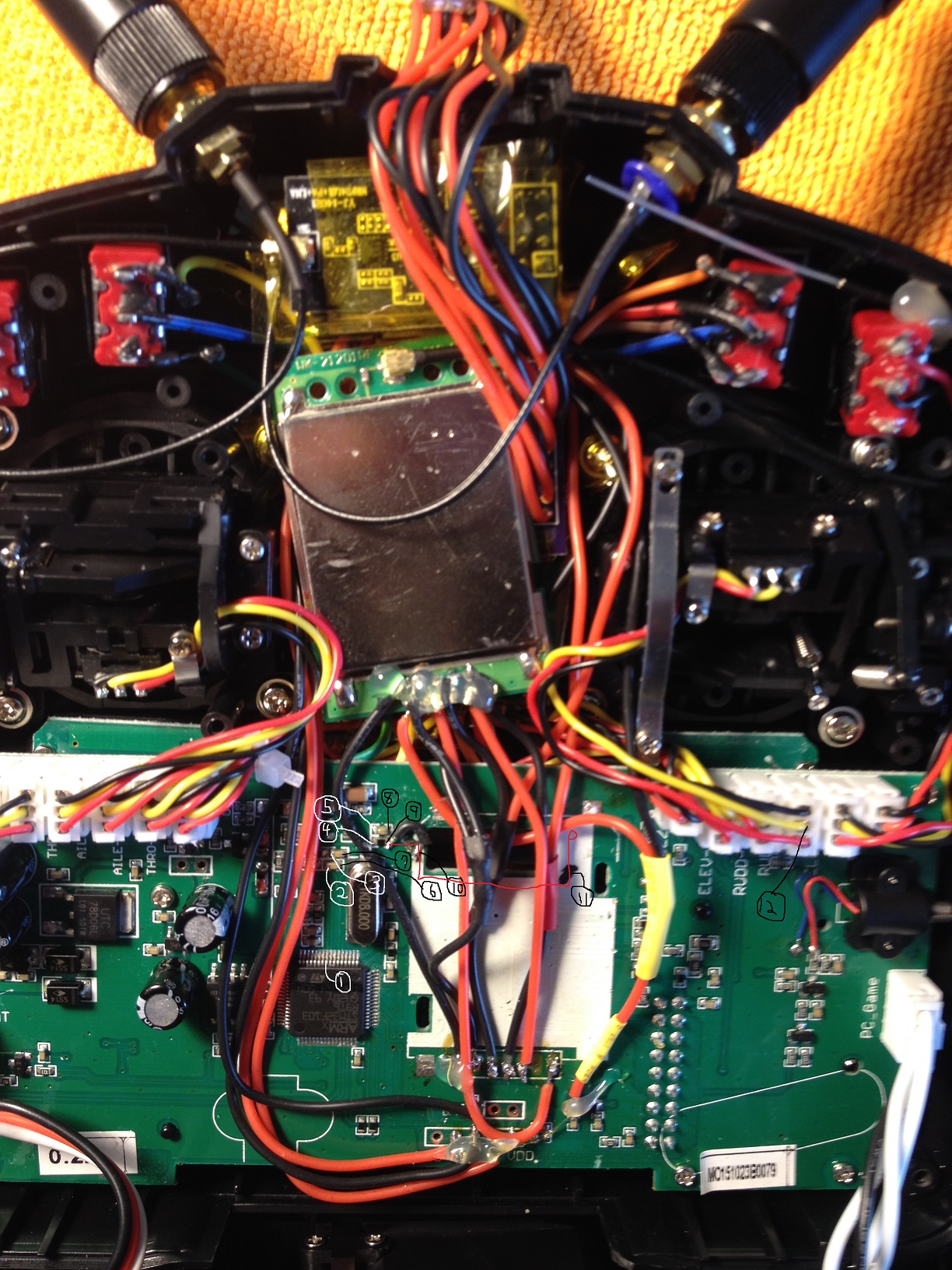
As requested, here is the path for the CPU (pin 9) to the THR control wire, as much as I was able to determine without taking out the board (I was lucky.)
Initially I started looking for the path at the THR (labeled ELEV) signal wire (point 12 in picture), but it must dive right to the bottom of the board as I can't see anything for sure.So I went over to the CPU and started with pin 9 (pt 1). It goes clearly straight up to 2 small components, and I got continuity at point 2 and point 3. Then I lose the trace (can you tell I never did this before?)
Because I had bridged a cut trace on the component at point 9 many weeks earlier when removing the stock CYRF, I took a shot and got continuity on my path on the left side of the component at pt 4 (and pt 5). I also got continuiy between points 6,7,8, but not 9. Wasn't sure if that meant I had a cold joint or the component didn't pass current (it was the only black one.) Didn't know if my solder joint had gone bad, or the other end of the bridge (pt 10) where I connected to the wire on the board had come loose. Hard to see since I had covered the whole thing with liquid electric tape and glue. The glue had been re-melted several times as I heat shrunk the wires for the MM and new CYRF, so I probably bumped the wire soldered to the board.
So I soldered in the new bridge on the right side of the component at pt 9 and to the board at pt 10. (Sounds simple doesn't it? LOL) I now got continuity between pin 9 and pt 4, but not pt 9 or farther. I also got continuity between pt 9, 10, 11, and 12. Point 11 was a scratch on the trace I made to test the original bridge (also covered with liq elec tape - documentation w/pics in link on page 1) Pretty happy with that, but without continuity from pt 1 to pt 12 really didn't expect this to work. Something right must have happened when I turned the power on!
The red line shows the part of the trace which goes under the stock CYRF and must dive to the other side of the board after pt 11.
Replied by misherman on topic Problem solved - now to learn how to pgm models...
As requested, here is the path for the CPU (pin 9) to the THR control wire, as much as I was able to determine without taking out the board (I was lucky.)
Initially I started looking for the path at the THR (labeled ELEV) signal wire (point 12 in picture), but it must dive right to the bottom of the board as I can't see anything for sure.So I went over to the CPU and started with pin 9 (pt 1). It goes clearly straight up to 2 small components, and I got continuity at point 2 and point 3. Then I lose the trace (can you tell I never did this before?)
Because I had bridged a cut trace on the component at point 9 many weeks earlier when removing the stock CYRF, I took a shot and got continuity on my path on the left side of the component at pt 4 (and pt 5). I also got continuiy between points 6,7,8, but not 9. Wasn't sure if that meant I had a cold joint or the component didn't pass current (it was the only black one.) Didn't know if my solder joint had gone bad, or the other end of the bridge (pt 10) where I connected to the wire on the board had come loose. Hard to see since I had covered the whole thing with liquid electric tape and glue. The glue had been re-melted several times as I heat shrunk the wires for the MM and new CYRF, so I probably bumped the wire soldered to the board.
So I soldered in the new bridge on the right side of the component at pt 9 and to the board at pt 10. (Sounds simple doesn't it? LOL) I now got continuity between pin 9 and pt 4, but not pt 9 or farther.
The red line shows the part of the trace which goes under the stock CYRF and must dive to the other side of the board after pt 11.
Last edit: 19 Jun 2016 04:13 by misherman. Reason: fixing error
- Forum
- News, Announcements and Feedback
- Feedback & Questions
- Throttle only responds to rudder movement ???
Time to create page: 0.201 seconds
-
Home

-
Forum
-
News, Announcements and Feedback
-
Feedback & Questions
- Throttle only responds to rudder movement ???