
- Posts: 62
Ham fisted de-soldering lifts 4 pads off a Devo 7E
- grnd flyr
-
Topic Author
- Offline
Less
More
24 Sep 2015 02:28 #38020
by grnd flyr
Ham fisted de-soldering lifts 4 pads off a Devo 7E was created by grnd flyr
Think I made a parts donor out of the one I was working on tonight, doggonit... Thought I had most of the solder wicked off, already lifted the back (antenna side) & was trying to lift the front, then poof... module lifted right up taking 4 pads with it.
It's tough when you learn while you're trying to learn... any hope for it? Too pooped for pics tonight if required... knew I shouldn't have gotten into it being tired, but...
It's tough when you learn while you're trying to learn... any hope for it? Too pooped for pics tonight if required... knew I shouldn't have gotten into it being tired, but...
- grnd flyr
-
- Offline
Less
More
- Posts: 62
25 Sep 2015 02:57 #38036
by grnd flyr
Replied by grnd flyr on topic Ham fisted de-soldering lifts 4 pads off a Devo 7E
Ok, so part two in my agony of defeat to ecstasy of victory soliloquy... erm, hoping so... there might be hope yet... ")
Got a flashlight in there tonight and could definitely see pads on the other side, cool! Now, to get to them... looks like you have to remove the LCD screen by unsoldering 327 pins which connect the two. Maybe the pin count is a little high... anyway if the LCD is removed I would have unfettered access to the pads.
Went out for a walk afterwards and it dawned on me that maybe, just maybe... if I angled the ends of some pre-stripped wrapping wire, and the L wasn't too long, I might be able to slide the wires flat between the LCD and PCB. Then at the hole location, rotate the wire and hopefully through the pad. If that works, just solder from the accessible side hoping capillary action will draw the solder between the wire and the hole then onto the pad. Manyana for that tho, maybe...
- Epyon
-
- Offline
Less
More
- Posts: 57
25 Sep 2015 03:47 #38038
by Epyon
Replied by Epyon on topic Ham fisted de-soldering lifts 4 pads off a Devo 7E
Which pads are lifted? Quite a few if not all of them should be traceable to vias or other spots on the board.
- grnd flyr
-
- Offline
Less
More
- Posts: 62
25 Sep 2015 11:46 #38048
by grnd flyr
Replied by grnd flyr on topic Ham fisted de-soldering lifts 4 pads off a Devo 7E
Early morning pic:

...thought it was 4 lifted, i'ts worse.
...thought it was 4 lifted, i'ts worse.
- Durete
-
- Offline
Less
More
- Posts: 610
25 Sep 2015 12:25 #38051
by Durete
Replied by Durete on topic Ham fisted de-soldering lifts 4 pads off a Devo 7E
With good soldering skills, I thought is easy to re-wire to the MCU pins.
All CYRF signals reach the pins inside my red circle. Some points are easy some others difficult")
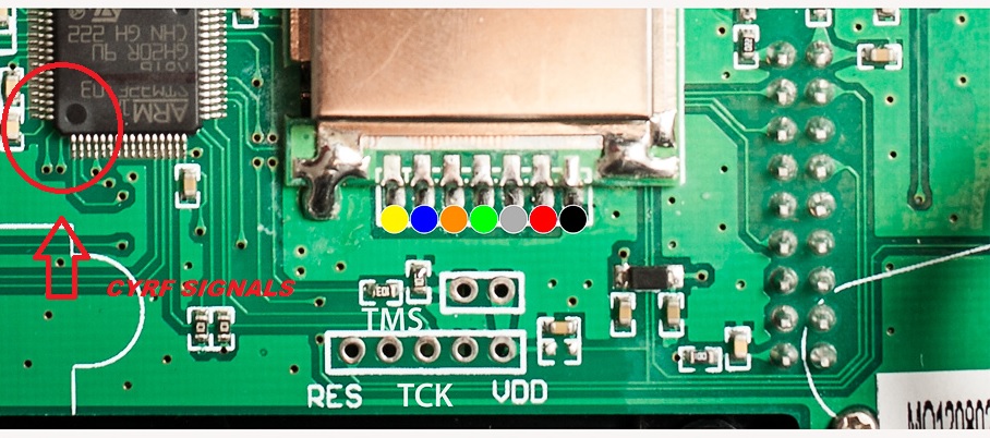
All CYRF signals reach the pins inside my red circle. Some points are easy some others difficult
- grnd flyr
-
- Offline
Less
More
- Posts: 62
25 Sep 2015 14:07 #38052
by grnd flyr
...slams on the brakes... ya, that precludes that option for me then... learning the ropes here.... Curious, how do/did you determine which pins go where?
Replied by grnd flyr on topic Ham fisted de-soldering lifts 4 pads off a Devo 7E
Durete wrote: With good soldering skills....
...slams on the brakes... ya, that precludes that option for me then... learning the ropes here....
- Durete
-
- Offline
Less
More
- Posts: 610
25 Sep 2015 14:23 #38053
by Durete
PB documented very good the hardware connections for all Devo TXs.
Here is the info about the 7e:
deviationtx.com/articles/17-hardware-doc...hardware-connections
You need this article and the ST MCU datasheet to find every pin.
Since I'm in the process to repair or replace my CYRF module (is dead without any use from some months ago ) , I traced some days ago the CYRF/MCU connections hoping to find the issue, but I can't find my hand notes
I will try trace again these connections ASAP, I guess will be useful for anyone.
Replied by Durete on topic Ham fisted de-soldering lifts 4 pads off a Devo 7E
grnd flyr wrote:
Durete wrote: With good soldering skills....
...slams on the brakes... ya, that precludes that option for me then... learning the ropes here....
PB documented very good the hardware connections for all Devo TXs.
Here is the info about the 7e:
deviationtx.com/articles/17-hardware-doc...hardware-connections
You need this article and the ST MCU datasheet to find every pin.
Since I'm in the process to repair or replace my CYRF module (is dead without any use from some months ago
I will try trace again these connections ASAP, I guess will be useful for anyone.
- Durete
-
- Offline
Less
More
- Posts: 610
25 Sep 2015 14:30 #38054
by Durete
Replied by Durete on topic Ham fisted de-soldering lifts 4 pads off a Devo 7E
By the way...
If anyone has a working spare 7e CyRF module...
I'm from Spain.

If anyone has a working spare 7e CyRF module...
I'm from Spain.
- grnd flyr
-
- Offline
Less
More
- Posts: 62
25 Sep 2015 14:44 #38055
by grnd flyr
Replied by grnd flyr on topic Ham fisted de-soldering lifts 4 pads off a Devo 7E
Durete, not one but 3... all are or will be replaced with 8S-Mod modules. I'm in the US, but they are yours if you want them, maybe you handle shipping?
Gotta go, hiho, off to work I go... back tonight...
Gotta go, hiho, off to work I go... back tonight...
- Durete
-
- Offline
Less
More
- Posts: 610
25 Sep 2015 14:56 #38056
by Durete
Great! I only need one Mine is dead, probably burned power amplifier. I ordered some RDAT212 ICs hoping to fix mine, but I'm not very confident.
I will send you a PM as soon as possible (I'm at job now ).
Replied by Durete on topic Ham fisted de-soldering lifts 4 pads off a Devo 7E
grnd flyr wrote: Durete, not one but 3...
Gotta go, hiho, off to work I go... back tonight...
Great! I only need one
I will send you a PM as soon as possible (I'm at job now
- Durete
-
- Offline
Less
More
- Posts: 610
26 Sep 2015 00:26 #38066
by Durete
Replied by Durete on topic Ham fisted de-soldering lifts 4 pads off a Devo 7E
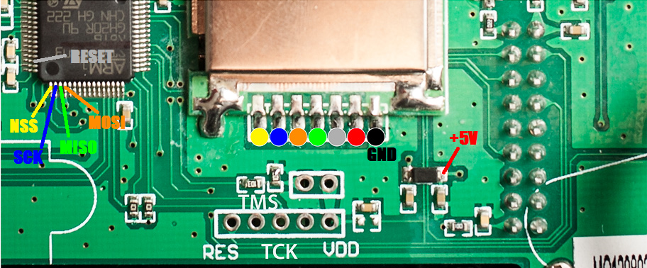
Ok, just trace again the CYRF signals to the MCU.
This time I didn't on paper
This time I didn't on paper
- grnd flyr
-
- Offline
Less
More
- Posts: 62
26 Sep 2015 00:58 #38067
by grnd flyr
Replied by grnd flyr on topic Ham fisted de-soldering lifts 4 pads off a Devo 7E
Very cool Durete, thanks a bunch!
- aMax
-
- Offline
Less
More
- Posts: 776
26 Sep 2015 09:05 - 26 Sep 2015 09:14 #38079
by aMax
Devo7e, TaranisQ X7, R9M , 4in1 MM, Futaba FC18plusV3.2 & DFT/FLD-02
Replied by aMax on topic Ham fisted de-soldering lifts 4 pads off a Devo 7E
I don't know why all these guys try to unsolder and lift the complette module.
I would suck most of the solder on the module and then use a Dremel or a sharp knife to cut the soldering part on the module.
After that, I am sure, the rest can be removed easily one by one...... or be used as new solder point.
Just my 2cent......
I would suck most of the solder on the module and then use a Dremel or a sharp knife to cut the soldering part on the module.
After that, I am sure, the rest can be removed easily one by one...... or be used as new solder point.
Just my 2cent......
Devo7e, TaranisQ X7, R9M , 4in1 MM, Futaba FC18plusV3.2 & DFT/FLD-02
Last edit: 26 Sep 2015 09:14 by aMax.
- Durete
-
- Offline
Less
More
- Posts: 610
26 Sep 2015 09:24 #38081
by Durete
Replied by Durete on topic Ham fisted de-soldering lifts 4 pads off a Devo 7E
I plain to remove using a super wide solder tip I have at job for my Pace station.
This solder tip reach all CYRF connections at time, should be easy adding a little bit of lead solder at time you melt the solder points.
This solder tip reach all CYRF connections at time, should be easy adding a little bit of lead solder at time you melt the solder points.
- grnd flyr
-
- Offline
Less
More
- Posts: 62
01 Oct 2015 13:17 #38312
by grnd flyr
Durete or anyone else that knows...
So, this little spot/pad dealie to the right of where Durete said to source 5+V, should I solder the wire to where the second arrow points here:

Pardon my ignorance, as I've said before, learning as I go... It looks like the spot was made to attach the wire but has that greenish varnishy stuff that's on the board covering it. Do I just lightly sand it or scrape it with an Xacto knife?
Or do I need to solder onto the right side of the pad where Durete originally pointed? Thanks again guys...
Replied by grnd flyr on topic Ham fisted de-soldering lifts 4 pads off a Devo 7E
Durete wrote: Ok, just trace again the CYRF signals to the MCU.
This time I didn't on paper
Durete or anyone else that knows...
So, this little spot/pad dealie to the right of where Durete said to source 5+V, should I solder the wire to where the second arrow points here:
Pardon my ignorance, as I've said before, learning as I go... It looks like the spot was made to attach the wire but has that greenish varnishy stuff that's on the board covering it. Do I just lightly sand it or scrape it with an Xacto knife?
Or do I need to solder onto the right side of the pad where Durete originally pointed? Thanks again guys...
- Arakon
-
- Offline
Less
More
- Posts: 305
01 Oct 2015 14:14 #38315
by Arakon
Replied by Arakon on topic Ham fisted de-soldering lifts 4 pads off a Devo 7E
Doesn't matter, they're connected. You can solder directly to the pin of that diode, which is likely easier than any other option.
However, watch out.. some modules need 3.3V rather than 5v.
However, watch out.. some modules need 3.3V rather than 5v.
- Durete
-
- Offline
Less
More
- Posts: 610
01 Oct 2015 16:51 - 01 Oct 2015 16:54 #38318
by Durete
Right! The right side from the diode is easier to solder, no need to use the "hole". This is a 5V alternative point, is the nearest 5V point (as far I know) to the 5V pad from the CYRF connection.
@grnd flyer and Arakon.
The CYRF module is powered from 5V (not exactly, because only reach the battery level minus a minor drop from a diode).
The external modules added (A7105, nRF24 and CC2500), are 3.3V modules, they can't be powered from the 5V point or will be fried.
Replied by Durete on topic Ham fisted de-soldering lifts 4 pads off a Devo 7E
grnd flyr wrote:
Durete wrote: Ok, just trace again the CYRF signals to the MCU.
This time I didn't on paper
Durete or anyone else that knows...
So, this little spot/pad dealie to the right of where Durete said to source 5+V, should I solder the wire to where the second arrow points here:
Pardon my ignorance, as I've said before, learning as I go... It looks like the spot was made to attach the wire but has that greenish varnishy stuff that's on the board covering it. Do I just lightly sand it or scrape it with an Xacto knife?
Or do I need to solder onto the right side of the pad where Durete originally pointed? Thanks again guys...
Right! The right side from the diode is easier to solder, no need to use the "hole". This is a 5V alternative point, is the nearest 5V point (as far I know) to the 5V pad from the CYRF connection.
@grnd flyer and Arakon.
The CYRF module is powered from 5V (not exactly, because only reach the battery level minus a minor drop from a diode).
The external modules added (A7105, nRF24 and CC2500), are 3.3V modules, they can't be powered from the 5V point or will be fried.
Last edit: 01 Oct 2015 16:54 by Durete. Reason: Typo
- grnd flyr
-
- Offline
Less
More
- Posts: 62
01 Oct 2015 20:32 #38328
by grnd flyr
Replied by grnd flyr on topic Ham fisted de-soldering lifts 4 pads off a Devo 7E
Thanks much Arakon & Durete! I should have mentioned CYRF/S-MOD so, yes 5V. I saw that hole there and it looked like it had to be linked & there on purpose, + maybe afraid of moving/removing the diode by mistake.
Felt it was better to ask than wish I did...
Felt it was better to ask than wish I did...
- RoGuE_StreaK
-
- Offline
Less
More
- Posts: 486
01 Oct 2015 21:01 #38332
by RoGuE_StreaK
Soldering to the diode will be much easier and safer.
Replied by RoGuE_StreaK on topic Ham fisted de-soldering lifts 4 pads off a Devo 7E
It's called a via and its purpose is to route a trace to the back of the board, where it can continue unimpeded to wherever it's going. Generally they use quite small drill holes, so may be difficult to get a wire in there. Also you don't know what's underneath, so sticking a wire through and soldering may increase the risk of shorting something. Unless you take the whole board out first.grnd flyr wrote: I saw that hole there and it looked like it had to be linked & there on purpose
Soldering to the diode will be much easier and safer.
- aMax
-
- Offline
Less
More
- Posts: 776
01 Oct 2015 21:13 #38333
by aMax
Devo7e, TaranisQ X7, R9M , 4in1 MM, Futaba FC18plusV3.2 & DFT/FLD-02
Replied by aMax on topic Ham fisted de-soldering lifts 4 pads off a Devo 7E
What are using, a 300W heat gun? A 30W iron with a fine tip should work even for this mod.grnd flyr wrote: Thanks much Arakon & Durete! I should have mentioned CYRF/S-MOD so, yes 5V. I saw that hole there and it looked like it had to be linked & there on purpose, + maybe afraid of moving/removing the diode by mistake.
Felt it was better to ask than wish I did...
Devo7e, TaranisQ X7, R9M , 4in1 MM, Futaba FC18plusV3.2 & DFT/FLD-02
Time to create page: 0.346 seconds
-
Home

-
Forum
-
General
-
General Discussions
- Ham fisted de-soldering lifts 4 pads off a Devo 7E