
- Posts: 152
Single-Board Universal Module
- mikemacwillie
-
- Offline
Less
More
02 Sep 2014 23:36 - 02 Sep 2014 23:37 #25473
by mikemacwillie
Replied by mikemacwillie on topic Single-Board Universal Module
All of my parts arrived today, including the back ordered MCUs from Digikey. Just waiting on the boards and stencil to arrive now.
Last edit: 02 Sep 2014 23:37 by mikemacwillie.
- PhracturedBlue
-
Topic Author
- Offline
Less
More
- Posts: 4403
09 Sep 2014 15:55 - 09 Sep 2014 15:57 #25567
by PhracturedBlue
Replied by PhracturedBlue on topic Single-Board Universal Module
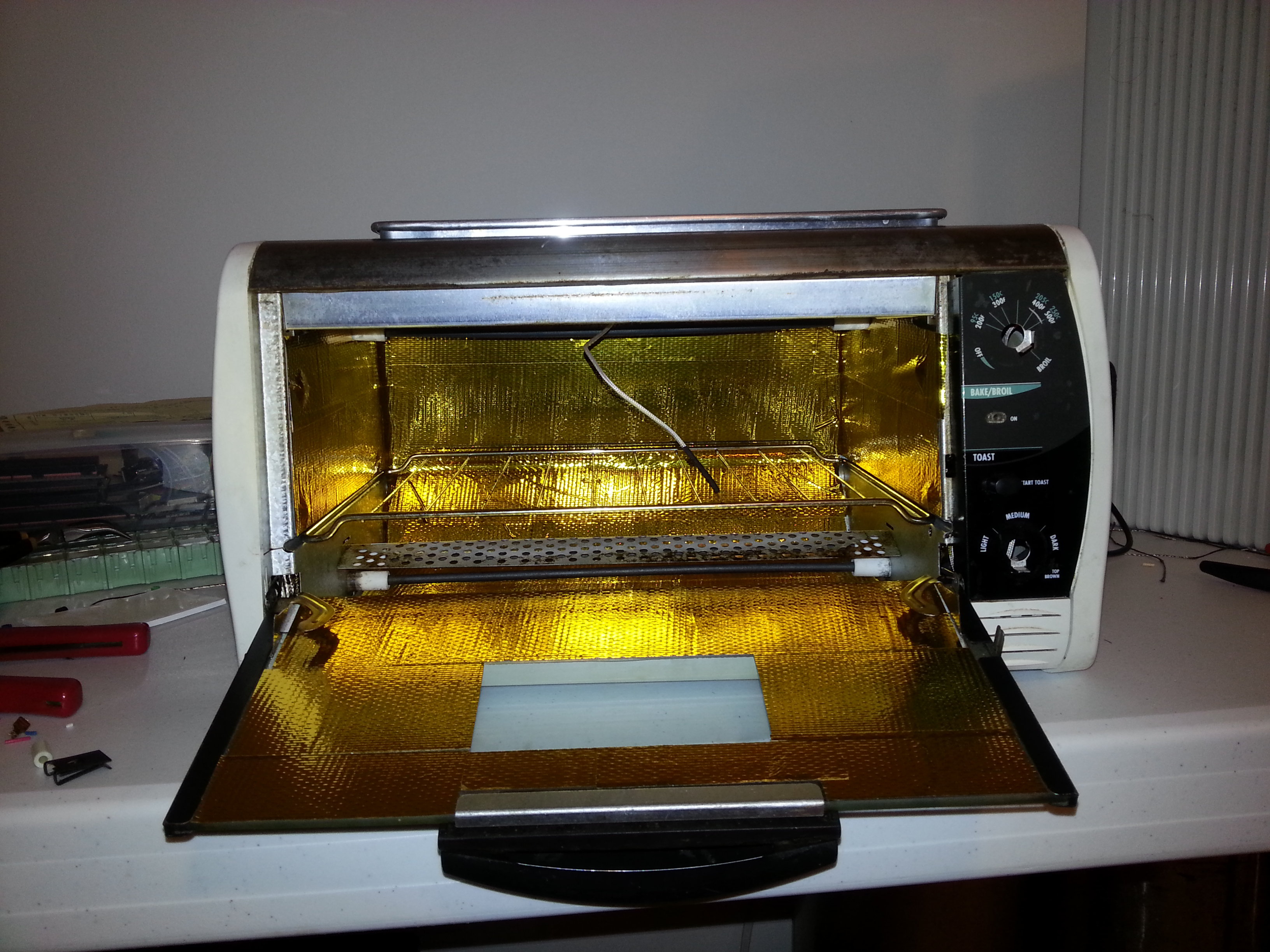
I got my boards yesterday (odd that I never got a shipping notice from batchpcb, they are usually good at that). I've got all the components, and I'm just waiting on the stencils which I only ordered on Sunday because I wasn't expecting the boards yet.
I finished building my reflow oven but I haven't calibrated it yet. Of course I have nearly no idea what I'm doing, so we'll see how assembly goes. Every time I look at the board and how tiny thepads are, I question my sanity.
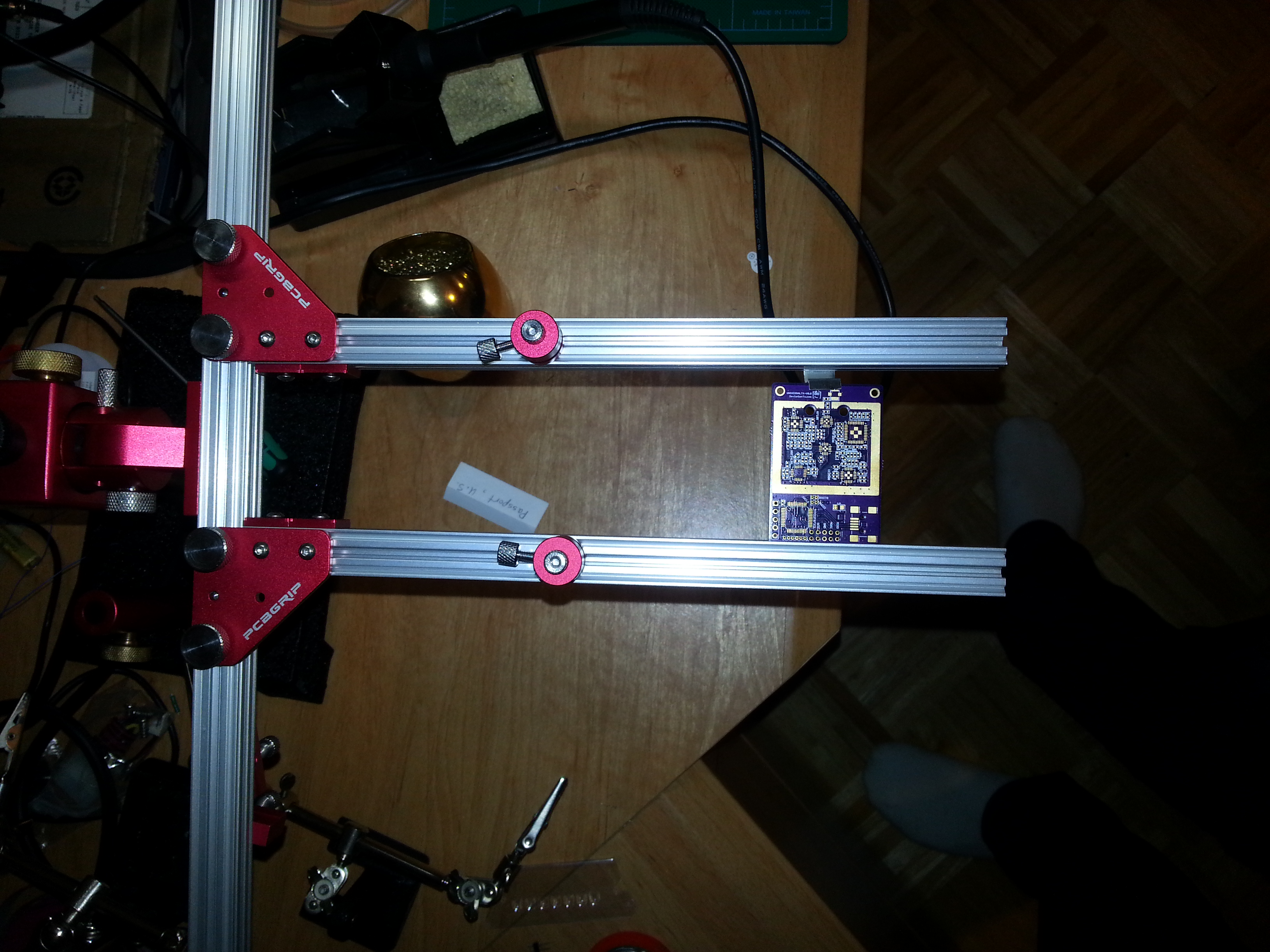
Board in my PCBGRIP jig (I love this jig):
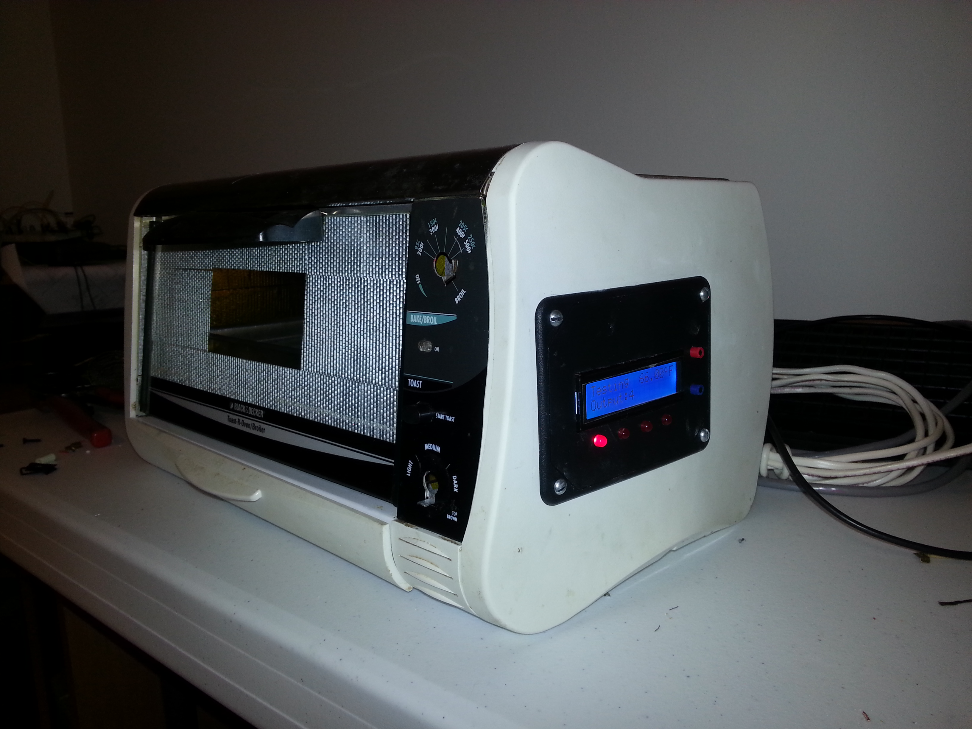
My oven with a ControLeo controller:
I finished building my reflow oven but I haven't calibrated it yet. Of course I have nearly no idea what I'm doing, so we'll see how assembly goes. Every time I look at the board and how tiny thepads are, I question my sanity.
Board in my PCBGRIP jig (I love this jig):
My oven with a ControLeo controller:
Last edit: 09 Sep 2014 15:57 by PhracturedBlue.
- mikemacwillie
-
- Offline
Less
More
- Posts: 152
09 Sep 2014 16:01 #25568
by mikemacwillie
Replied by mikemacwillie on topic Single-Board Universal Module
Hopefully that means I'll get mine soon. I'd assume ours were both on the same panel given that we ordered them within a day or so. I'm in Canada, so their PCBs take a little longer to get up here. I haven't received my Stencils yet either, and I ordered them the day after the PCBs.
That jig looks much nicer than the Panavise I use... Might have to look at buying one of those.
That jig looks much nicer than the Panavise I use... Might have to look at buying one of those.
- victzh
-
- Offline
Less
More
- Posts: 1386
09 Sep 2014 16:31 #25572
by victzh
Replied by victzh on topic Single-Board Universal Module
PhracturedBlue, these feelings like you don't know what you're doing are very, very familiar. The pads are of frightening size, and the number of components to place by hand is challenging.
My first board designed and built was very complicated and contained many small RF components. But it worked! I used hot plate and did not calibrate it, I also did not used stencil, so your approach is much more professional and should work better.
Admittedly, your board is many times more complicated than typical RF board, but we hope it's feasible and wish you luck!
- PhracturedBlue
-
- Offline
Less
More
- Posts: 4403
09 Sep 2014 16:56 #25575
by PhracturedBlue
I had always planned to get a panavise, but then I saw the PCBGRIP. It is really well designed, is very stable, and has lots of attachments that make it easy to hold parts in place for soldering. It is not cheap, but I am so glad I bought it.
I'm still not sure what to do with the bottom of the board. I bought a stencil for it, but my guess is I'll try soldering it by hand. The other option I may explore is using low-temp Bismuth solder (ChipQuik) for the bottom of the board, and reflowing the top 1st using normal leaded solder, then reflowing the bottom at low temperature. The bismuth solders melt at 138C which would likely be fine for everything except maybe the LDO (which is easy to hand-solder).
Replied by PhracturedBlue on topic Single-Board Universal Module
mikemacwillie wrote: That jig looks much nicer than the Panavise I use... Might have to look at buying one of those.
I had always planned to get a panavise, but then I saw the PCBGRIP. It is really well designed, is very stable, and has lots of attachments that make it easy to hold parts in place for soldering. It is not cheap, but I am so glad I bought it.
I'm still not sure what to do with the bottom of the board. I bought a stencil for it, but my guess is I'll try soldering it by hand. The other option I may explore is using low-temp Bismuth solder (ChipQuik) for the bottom of the board, and reflowing the top 1st using normal leaded solder, then reflowing the bottom at low temperature. The bismuth solders melt at 138C which would likely be fine for everything except maybe the LDO (which is easy to hand-solder).
- mikemacwillie
-
- Offline
Less
More
- Posts: 152
09 Sep 2014 17:02 #25577
by mikemacwillie
Replied by mikemacwillie on topic Single-Board Universal Module
I didn't bother with a stencil for the bottom, I'll just solder it by hand. If you're going to reflow it, you don't need to worry about using a bismuth based low temperature solder for the bottom. The surface tension of the molten solder will hold the components to the other side during relow, unless they're really heavy. There are surface mount adhesives that you can use for heavy parts to keep them from falling off. I'd recommend just hand soldering them though. Make sure you have a good liquid or gel flux.
- PhracturedBlue
-
- Offline
Less
More
- Posts: 4403
09 Sep 2014 17:21 #25578
by PhracturedBlue
Replied by PhracturedBlue on topic Single-Board Universal Module
the potential issue with hand-soldering is the crystals. I'm not sure you can get at the pads with an iron. we'll see.
- mikemacwillie
-
- Offline
Less
More
- Posts: 152
09 Sep 2014 19:21 #25581
by mikemacwillie
Replied by mikemacwillie on topic Single-Board Universal Module
Yeah, those are probably going to require a hot air gun to hand solder them.
- victzh
-
- Offline
Less
More
- Posts: 1386
10 Sep 2014 20:24 #25604
by victzh
Replied by victzh on topic Single-Board Universal Module
You have an oven, not a hot plate. You actually can just place crystals on the regular soldering paste and they indeed will be kept in place by surface tension. The only extra in this case - the board should be exposed to the heat on both sides, so it should be kept at the corners or by the mounting holes.
- Fernandez
-
- Offline
Less
More
- Posts: 983
10 Sep 2014 21:30 #25608
by Fernandez
Replied by Fernandez on topic Single-Board Universal Module
I also use a normal oven. after flowing open the door as the solder should only be short time at peak temp.
I recommend to use old style leaded solder with few % silver. Do buy from good supplier (not use chines or no brand nme stuff) and buy fresh stuff. I can tell you it realy makes a difference, it must be fresh for the best flow.
Supply by hand works fine use small needle/syringe, very little bit is enough only at the outerpins of the ic's. i always clean the pcb with some liquid flux before putting the solder paste.
you can use usb microscope to check for solder bridges.
- PhracturedBlue
-
- Offline
Less
More
- Posts: 4403
11 Sep 2014 17:55 #25619
by PhracturedBlue
Replied by PhracturedBlue on topic Single-Board Universal Module
Not having done this before, do you do the bottom of the board 1st then? There are only a few elements on the bottom of the board, and they are all either very small or have large solder surface area, so I guess the surface tension should be fine. I would be much more worried about all the qfn parts being upside-down in the oven. If they move, it'll be a mess.victzh wrote: You have an oven, not a hot plate. You actually can just place crystals on the regular soldering paste and they indeed will be kept in place by surface tension. The only extra in this case - the board should be exposed to the heat on both sides, so it should be kept at the corners or by the mounting holes.
- mikemacwillie
-
- Offline
Less
More
- Posts: 152
11 Sep 2014 21:25 #25623
by mikemacwillie
Replied by mikemacwillie on topic Single-Board Universal Module
Yeah, that'd be a good idea. It's actually quite surprising the first time how much can be held on by the surface tension of the molten solder alone. You don't have to be super precise with your placement either. As long as they're on the correct pad, in the paste and not touching an adjacent pad, they will float into center.
- billmester
-
- Offline
Less
More
- Posts: 215
12 Sep 2014 04:59 #25625
by billmester
Replied by billmester on topic Single-Board Universal Module
Hi
google "chipbonder".
Helps a lot.")
bm
google "chipbonder".
Helps a lot.
bm
- victzh
-
- Offline
Less
More
- Posts: 1386
12 Sep 2014 22:40 #25631
by victzh
Replied by victzh on topic Single-Board Universal Module
I don't have oven, only hot plate. The surface tension is quite high to align small quads to the pads. The only critical moment is between the solder paste is dried and melting. Then the adhesion is minimal. It's also important to observe the intermediate plato on the temp curve - it allows the paste to dry without extensive vapor bursts - I once heated the board too fast and several resistors and caps were lifted by the vapor burst.
I think crystals and small elements on the bottom is the right way to do it.
I think crystals and small elements on the bottom is the right way to do it.
- PhracturedBlue
-
- Offline
Less
More
- Posts: 4403
14 Sep 2014 00:11 - 14 Sep 2014 00:11 #25643
by PhracturedBlue
Replied by PhracturedBlue on topic Single-Board Universal Module
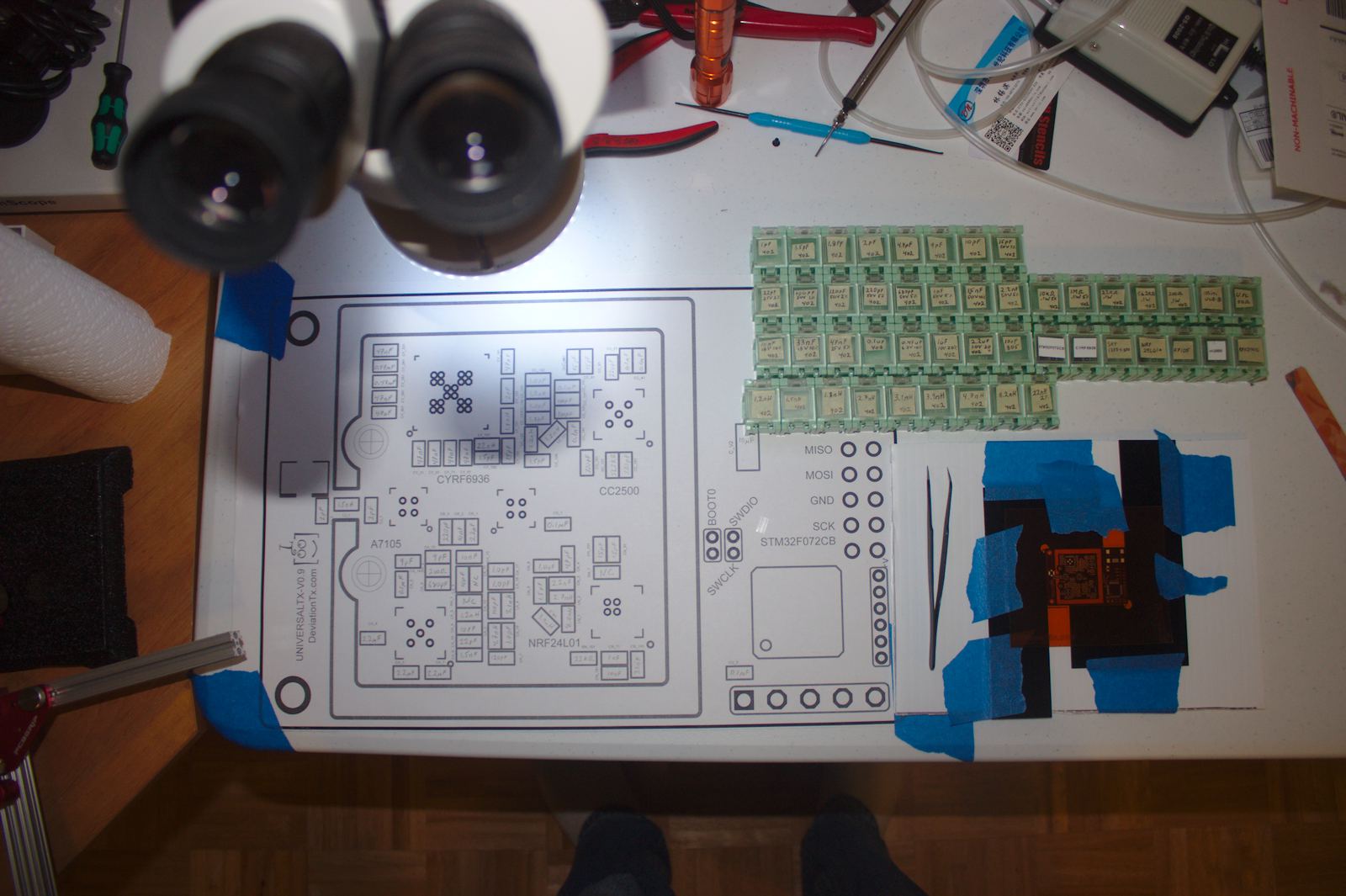
I got my stencils, and placed and reflowed the bottom of the board. Everything seems to have gone well, and got a bit of a feel for what it'll take to do the top. Spent most of the day moving components from the tape to little smd boxes and labeling everything. I have a vacuum to extract pieces from the tape, but I'm not happy with the control on the small pieces, so I guess it'll be tweezers all the way.
Anyhow, I've now got everything setup to place the main board. I'll likely wait until tomorrow though and give my shoulders a break.
Anyhow, I've now got everything setup to place the main board. I'll likely wait until tomorrow though and give my shoulders a break.
Last edit: 14 Sep 2014 00:11 by PhracturedBlue.
- mikemacwillie
-
- Offline
Less
More
- Posts: 152
14 Sep 2014 00:19 #25644
by mikemacwillie
Replied by mikemacwillie on topic Single-Board Universal Module
I have that exact same vacuum system. It's not bad on the bigger stuff, but I've found the same thing, tweezers are way better for control of the small stuff. It's hard to rotate them with the vacuum pickup. I find that after aligning the part, if you kind of stick one of the jaws to the solder mask and only move the other jaw, you won't knock the part off while lifting the tweezers as often. The scaled up print of the silkscreen is really handy, I don't like to build without one.
Sadly my boards didn't arrive before the weekend. I got my stencil on Friday, so hopefully the boards show up next week, so I can knock out my boards on Saturday.
Sadly my boards didn't arrive before the weekend. I got my stencil on Friday, so hopefully the boards show up next week, so I can knock out my boards on Saturday.
- PhracturedBlue
-
- Offline
Less
More
- Posts: 4403
14 Sep 2014 05:49 - 14 Sep 2014 05:49 #25646
by PhracturedBlue
Replied by PhracturedBlue on topic Single-Board Universal Module
Well, 2 hours of nerve-racking placement, and a very sore neck, and I got the board placed and reflowed. I haven't done a detailed inspection yet, but at 1st glance, it actually looks like it worked really well despite my pushing components all over the place to get things aligned. I only lost 2 components due to tweezer launch, so I'm pretty happy with that. I did find that my stencil is missing a cutout for paste on the rfx2401c and skyworks chip. I didn't have a syringe handy, but was able to scrape a bit of paste onto the pads. Anyhow, I won't be able to actually examine the board until tomorrow, but I think this was pretty good work for today.
Last edit: 14 Sep 2014 05:49 by PhracturedBlue.
- SeByDocKy
-
- Offline
Less
More
- Posts: 1016
14 Sep 2014 07:40 #25647
by SeByDocKy
Thumbs up
Replied by SeByDocKy on topic Single-Board Universal Module
PhracturedBlue wrote: Well, 2 hours of nerve-racking placement, and a very sore neck, and I got the board placed and reflowed. I haven't done a detailed inspection yet, but at 1st glance, it actually looks like it worked really well despite my pushing components all over the place to get things aligned. I only lost 2 components due to tweezer launch, so I'm pretty happy with that. I did find that my stencil is missing a cutout for paste on the rfx2401c and skyworks chip. I didn't have a syringe handy, but was able to scrape a bit of paste onto the pads. Anyhow, I won't be able to actually examine the board until tomorrow, but I think this was pretty good work for today.
Thumbs up
- PhracturedBlue
-
- Offline
Less
More
- Posts: 4403
14 Sep 2014 19:09 #25657
by PhracturedBlue
Replied by PhracturedBlue on topic Single-Board Universal Module
Major setback. The board has a power-ground short. I checked it caefully, and haven't found it yet. I tested the un-populated boards and one of the other 2 also has a power-ground short. I'll carefully look it over and see if I can locate it visually. I thought I had checked the board before I assembled it, but I now think I only verified the 5V supply.
- mikemacwillie
-
- Offline
Less
More
- Posts: 152
14 Sep 2014 19:28 - 14 Sep 2014 19:55 #25658
by mikemacwillie
Replied by mikemacwillie on topic Single-Board Universal Module
Well, that's a bit concerning. A 66% failure rate does not look good for a PCB manufacturer.. Might be worth contacting them and seeing what they say. I'll be sure to check mine when they get here. I don't expect they'll be much better, given the high probability of them being on the same panel. If mine are crap too, it might be worth splitting a run of 10 from one of the other fabs.
I checked over the Eagle files, and there are quite a few clearance errors, but they're all the same signal, so they're not likely an issue. There's a fairly strong possibility that it's a layer registration issue, and the short will be on the internal layers.
I checked over the Eagle files, and there are quite a few clearance errors, but they're all the same signal, so they're not likely an issue. There's a fairly strong possibility that it's a layer registration issue, and the short will be on the internal layers.
Last edit: 14 Sep 2014 19:55 by mikemacwillie.
Time to create page: 1.398 seconds
-
Home

-
Forum
-
Development
-
Development
- Single-Board Universal Module