
- Posts: 857
Extra inputs for Devo Tx's
- Deal57
-
- Offline
Less
More
05 Sep 2015 00:01 #37452
by Deal57
Deviation Devo7e 3way switch mod, A7105, NRF24L01
Devo6s 2x2 switch mod, trim mod, haptic, multimodule, A7105, NRF24L01, CC2500
Devo12e 4-in-1 with voice mod -- it speaks!!
Replied by Deal57 on topic Extra inputs for Devo Tx's
I finally completed the last modification to my external controls. The current configuration is 2 potentiometers, 1 6-position switch, 2 x 3-way switches, 1 2-way switch. The latest addition is a panel with six individual momentary switches and six LED indicators.
This panel, seen here in my prototype, was built using just SIX digital pins on the Arduino Pro Mini! The "Charlieplexing" approach took me some time to wrap my head around, but it is very functional and particularly useful since i'm already using diodes. This lets me use a short 6-conductor cable from the Arduino (or enclosure) to the switch panel, presumably allowing me to position it better on my GCS (if I ever get there!). The pots and switches run without regard to this new panel, and in Devo you can continue to mix as desired.
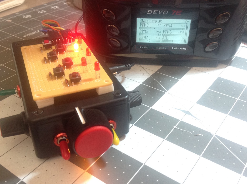
I've set the LEDs to come on based on the mode selected. For the momentary switches, I capture the switch pressed and set the mode value, which corresponds to a particular number of milliseconds in the PPM stream. Since the switch sets a mode, and the LEDs take action based on that mode at the same time the PPM stream is built, it seems like monitoring the PPM stream would be redundant. In any case, I've tried this with an APM flight controller and it works great.
All that being said, the functionality is terrific; the real problem now is how to package it and make it useful.
At this point I just want to find the "right" enclosure. I am thinking of a box with a USB jack, a 6-pin connector of some sort and possibly a battery or charging port. but I guess it depends on what I find. I guess it is time for that 3-D printer?
Happy flying!
This panel, seen here in my prototype, was built using just SIX digital pins on the Arduino Pro Mini! The "Charlieplexing" approach took me some time to wrap my head around, but it is very functional and particularly useful since i'm already using diodes. This lets me use a short 6-conductor cable from the Arduino (or enclosure) to the switch panel, presumably allowing me to position it better on my GCS (if I ever get there!). The pots and switches run without regard to this new panel, and in Devo you can continue to mix as desired.
I've set the LEDs to come on based on the mode selected. For the momentary switches, I capture the switch pressed and set the mode value, which corresponds to a particular number of milliseconds in the PPM stream. Since the switch sets a mode, and the LEDs take action based on that mode at the same time the PPM stream is built, it seems like monitoring the PPM stream would be redundant. In any case, I've tried this with an APM flight controller and it works great.
All that being said, the functionality is terrific; the real problem now is how to package it and make it useful.
At this point I just want to find the "right" enclosure. I am thinking of a box with a USB jack, a 6-pin connector of some sort and possibly a battery or charging port. but I guess it depends on what I find. I guess it is time for that 3-D printer?
Happy flying!
Deviation Devo7e 3way switch mod, A7105, NRF24L01
Devo6s 2x2 switch mod, trim mod, haptic, multimodule, A7105, NRF24L01, CC2500
Devo12e 4-in-1 with voice mod -- it speaks!!
- mwm
-
Topic Author
- Offline
05 Sep 2015 00:31 #37453
by mwm
Do not ask me questions via PM. Ask in the forums, where I'll answer if I can.
My remotely piloted vehicle ("drone") is a yacht.
Replied by mwm on topic Extra inputs for Devo Tx's
Do not ask me questions via PM. Ask in the forums, where I'll answer if I can.
My remotely piloted vehicle ("drone") is a yacht.
- Epyon
-
- Offline
Less
More
- Posts: 57
05 Sep 2015 01:36 #37455
by Epyon
Replied by Epyon on topic Extra inputs for Devo Tx's
Nice work Deal57.
Still revamping my 7e. I swapped to a Taranis 6-way switch like you. Kind of a fidgety lil POS don't you think? I really dislike the jump to low position between most switchings. Gotta work some debounce into my code.
Currently at three potentiometers, 6-way "switch", three 3-ways, one 2-way, and two momentary buttons run through the Arduino. Then two 3-ways, two momentary buttons and the standard two 2-ways hooked to the 7e itself. Heh.
Also got a 128x32 OLED working.
The audio board plan is stalled, as mine arrived DOA. Definitely still on the agenda down the road.
Still waiting on an I2C voltage current sensor which I'll stuff, along with a real time clock module and possibly a 9DOF module into the unused battery bay of my FPV monitor. Good times, good times.
Still revamping my 7e. I swapped to a Taranis 6-way switch like you. Kind of a fidgety lil POS don't you think? I really dislike the jump to low position between most switchings. Gotta work some debounce into my code.
Currently at three potentiometers, 6-way "switch", three 3-ways, one 2-way, and two momentary buttons run through the Arduino. Then two 3-ways, two momentary buttons and the standard two 2-ways hooked to the 7e itself. Heh.

Also got a 128x32 OLED working.
The audio board plan is stalled, as mine arrived DOA. Definitely still on the agenda down the road.
Still waiting on an I2C voltage current sensor which I'll stuff, along with a real time clock module and possibly a 9DOF module into the unused battery bay of my FPV monitor. Good times, good times.
- davidwyl
-
- Offline
Less
More
- Posts: 26
08 Sep 2015 11:31 - 08 Sep 2015 12:56 #37567
by davidwyl
(i have no experience arduino programming)
2. will this code (version 2.5) work on arduino nano?
Replied by davidwyl on topic Extra inputs for Devo Tx's
1. my plan is to add 2 pot & two 3ways switch, any modification needed to this code?Deal57 wrote: I finally completed the last modification to my external controls. The current configuration is 2 potentiometers, 1 6-position switch, 2 x 3-way switches, 1 2-way switch. The latest addition is a panel with six individual momentary switches and six LED indicators.
I've set the LEDs to come on based on the mode selected. For the momentary switches, I capture the switch pressed and set the mode value, which corresponds to a particular number of milliseconds in the PPM stream. Since the switch sets a mode, and the LEDs take action based on that mode at the same time the PPM stream is built, it seems like monitoring the PPM stream would be redundant. In any case, I've tried this with an APM flight controller and it works great.
All that being said, the functionality is terrific; the real problem now is how to package it and make it useful.
At this point I just want to find the "right" enclosure. I am thinking of a box with a USB jack, a 6-pin connector of some sort and possibly a battery or charging port. but I guess it depends on what I find. I guess it is time for that 3-D printer?
Happy flying!
(i have no experience arduino programming)
2. will this code (version 2.5) work on arduino nano?
Last edit: 08 Sep 2015 12:56 by davidwyl.
- Deal57
-
- Offline
Less
More
- Posts: 857
08 Sep 2015 13:06 #37569
by Deal57
Deviation Devo7e 3way switch mod, A7105, NRF24L01
Devo6s 2x2 switch mod, trim mod, haptic, multimodule, A7105, NRF24L01, CC2500
Devo12e 4-in-1 with voice mod -- it speaks!!
Replied by Deal57 on topic Extra inputs for Devo Tx's
I presume that you mean that you'll be adding the switches and pots using the Arduino. The code that we're using will work, you just have to use the correct pins on the Arduino. Obviously there is more in the code than you need, but I don't think the extra non-functioning code will affect your controls. PLEASE test first. I left some commented code (lines start with "//") that turn on the serial port and print back the values reported by each switch/pot; just uncomment them and use the Serial Monitor function in the IDE tools.
The Arduino code is very simple to learn and with a bit of practice you'l be programming it yourself. The Arduino site has a wealth of examples and references, as well as some really great projects. I've programmed stuff for years, so for Arduino I started by doing a few exercises in the Learning menu and things made sense pretty quickly.
The Arduino code is very simple to learn and with a bit of practice you'l be programming it yourself. The Arduino site has a wealth of examples and references, as well as some really great projects. I've programmed stuff for years, so for Arduino I started by doing a few exercises in the Learning menu and things made sense pretty quickly.
Deviation Devo7e 3way switch mod, A7105, NRF24L01
Devo6s 2x2 switch mod, trim mod, haptic, multimodule, A7105, NRF24L01, CC2500
Devo12e 4-in-1 with voice mod -- it speaks!!
- davidwyl
-
- Offline
Less
More
- Posts: 26
08 Sep 2015 14:23 #37570
by davidwyl
Will load v2.5 code into Arduino nano.
2pot connect to A1 & A2.
2x3ways connect to D6-D7 & D8-D9.
Correct?
Did u add capacitor to the vin & pot 5v?
Replied by davidwyl on topic Extra inputs for Devo Tx's
Deal57 wrote: I presume that you mean that you'll be adding the switches and pots using the Arduino. The code that we're using will work, you just have to use the correct pins on the Arduino. Obviously there is more in the code than you need, but I don't think the extra non-functioning code will affect your controls. PLEASE test first. I left some commented code (lines start with "//") that turn on the serial port and print back the values reported by each switch/pot; just uncomment them and use the Serial Monitor function in the IDE tools.
Will load v2.5 code into Arduino nano.
2pot connect to A1 & A2.
2x3ways connect to D6-D7 & D8-D9.
Correct?
Did u add capacitor to the vin & pot 5v?
- Deal57
-
- Offline
Less
More
- Posts: 857
09 Sep 2015 02:55 #37578
by Deal57
Those are the correct connections. I did not use a capacitor as I am using a battery in an external box and I cannot track down specifics to help me understand the problem I am solving. It's probably a good idea.
Deviation Devo7e 3way switch mod, A7105, NRF24L01
Devo6s 2x2 switch mod, trim mod, haptic, multimodule, A7105, NRF24L01, CC2500
Devo12e 4-in-1 with voice mod -- it speaks!!
Replied by Deal57 on topic Extra inputs for Devo Tx's
davidwyl wrote:
Deal57 wrote: I presume that you mean that you'll be adding the switches and pots using the Arduino. The code that we're using will work, you just have to use the correct pins on the Arduino. Obviously there is more in the code than you need, but I don't think the extra non-functioning code will affect your controls. PLEASE test first. I left some commented code (lines start with "//") that turn on the serial port and print back the values reported by each switch/pot; just uncomment them and use the Serial Monitor function in the IDE tools.
Will load v2.5 code into Arduino nano.
2pot connect to A1 & A2.
2x3ways connect to D6-D7 & D8-D9.
Correct?
Did u add capacitor to the vin & pot 5v?
Those are the correct connections. I did not use a capacitor as I am using a battery in an external box and I cannot track down specifics to help me understand the problem I am solving. It's probably a good idea.
Deviation Devo7e 3way switch mod, A7105, NRF24L01
Devo6s 2x2 switch mod, trim mod, haptic, multimodule, A7105, NRF24L01, CC2500
Devo12e 4-in-1 with voice mod -- it speaks!!
- Epyon
-
- Offline
Less
More
- Posts: 57
09 Sep 2015 04:29 #37579
by Epyon
You can strip out a lot of Ian's original code, such as the dual rate stuff. Having inputs, especially analogs, active with no input can sometimes make everything go wonky.
For 2 pots and 2 3-ways, here's about all you'll need.
122 lines of code.
Compared to 194 in Ian's, and 545 in my current...............
Replied by Epyon on topic Extra inputs for Devo Tx's
davidwyl wrote: Will load v2.5 code into Arduino nano.
2pot connect to A1 & A2.
2x3ways connect to D6-D7 & D8-D9.
Correct?
Did u add capacitor to the vin & pot 5v?
You can strip out a lot of Ian's original code, such as the dual rate stuff. Having inputs, especially analogs, active with no input can sometimes make everything go wonky.
For 2 pots and 2 3-ways, here's about all you'll need.
// Devo 7e PPM input
// For use with Arduino Nano V3.0
// Based on sketch by Ian Johnston

// Analog pin assignments
int AI_Pin_A1 = 2;    // potentiometer #1 pin
int AI_Pin_A2 = 3;    // potentiometer #2 pin
int AI_Raw_A1;        // Analog In raw var - 0->1023....
int AI_Raw_A2;
int A1_uS = 750;      // potentiometer #1 us
int A2_uS = 750;      // potentiometer #2 us
int sw1_uS = 750;     // 3-way switch #1 us
int sw2_uS = 750;     // 3-way switch #2 us


int Fixed_uS = 300;       // PPM frame fixed LOW phase
int pulseMin = 750;       // pulse minimum width minus start in uS
int pulseMax = 1700;      // pulse maximum width in uS

// Digital pin assignments
int outPinPPM = 10;     // PPM out
int inPinD2 = 2;        // 3-way switch #1 pin for position 1. Positions 1 and 3 combine for middle position.
int inPinD3 = 3;        // 3-way switch #1 pin for position 3
int inPinD4 = 4;        // 3-way switch #2 pin for position 1
int inPinD5 = 5;        // 3-way switch #2 pin for position 3

ISR(TIMER1_COMPA_vect) {
    ppmoutput(); // Jump to ppmoutput subroutine
}

void setup() {

  pinMode(outPinPPM, OUTPUT);   // sets the digital pin as output
  pinMode(inPinD2, INPUT);      // sets the digital pin as input
  digitalWrite(inPinD2, HIGH);  // turn on pull-up resistor
  pinMode(inPinD3, INPUT);
  digitalWrite(inPinD3, HIGH);
  pinMode(inPinD4, INPUT);
  digitalWrite(inPinD4, HIGH);
  pinMode(inPinD5, INPUT);
  digitalWrite(inPinD5, HIGH);

   // Setup timer
  TCCR1A = B00110001; // Compare register B used in mode '3'
  TCCR1B = B00010010; // WGM13 and CS11 set to 1
  TCCR1C = B00000000; // All set to 0
  TIMSK1 = B00000010; // Interrupt on compare B
  TIFR1  = B00000010; // Interrupt on compare B
  OCR1A = 22000; // 22mS PPM output refresh
  OCR1B = 1000;
}

void ppmoutput() { // PPM output sub routine

 // Channel 1 - Analog 1
  digitalWrite(outPinPPM, LOW);
  delayMicroseconds(Fixed_uS);    // Hold
  digitalWrite(outPinPPM, HIGH);
  delayMicroseconds(A1_uS);  // Hold for A1_uS microseconds

 // Channel 2 - Analog 2
  digitalWrite(outPinPPM, LOW);
  delayMicroseconds(Fixed_uS);    // Hold
  digitalWrite(outPinPPM, HIGH);
  delayMicroseconds(A2_uS); // Hold for A2_uS microseconds

// Channel 3 - 3-way switch #1
  digitalWrite(outPinPPM, LOW);
  delayMicroseconds(Fixed_uS);    // Hold
  digitalWrite(outPinPPM, HIGH);
  delayMicroseconds(sw1_uS);     // Hold for sw1_uS microseconds

// Channel 4 - 3-way switch #2
  digitalWrite(outPinPPM, LOW);
  delayMicroseconds(Fixed_uS);    // Hold
  digitalWrite(outPinPPM, HIGH);
  delayMicroseconds(sw2_uS);     // Hold for sw2_uS microseconds

// Synchro pulse
  digitalWrite(outPinPPM, LOW);
  delayMicroseconds(Fixed_uS);    // Hold
  digitalWrite(outPinPPM, HIGH);  // Start Synchro pulse
}

void loop() { // Main loop

 // Read analog pins
   AI_Raw_A1 = analogRead(AI_Pin_A1);
   AI_Raw_A2 = analogRead(AI_Pin_A2);

 // Map analog inputs to PPM rates for each of the channels
   A1_uS = AI_Raw_A1 + pulseMin;
   A2_uS = AI_Raw_A2 + pulseMin;

 // Potentiometer limits
  if (A1_uS <= 750) A1_uS = 750;     // Min
  if (A1_uS >= 1625) A1_uS = 1625;   // Max
  if (A2_uS <= 750) A2_uS = 750;
  if (A2_uS >= 1625) A2_uS = 1625;

// 3-way switch #1
  if (digitalRead(inPinD2) == 0) {
           sw1_uS = 750;
 }
  if ((digitalRead(inPinD2) == 1) && (digitalRead(inPinD3) == 1)) {
           sw1_uS = 1190;                 // Center us, may need to adjust this
 }
  if (digitalRead(inPinD3) == 0) {
           sw1_uS = 1625;
 }

// 3-way switch #2
  if (digitalRead(inPinD4) == 0) {
           sw2_uS = 750;
 }
  if ((digitalRead(inPinD4) == 1) && (digitalRead(inPinD5) == 1)) {
           sw2_uS = 1190;                 // Center us, may need to adjust this
 }
  if (digitalRead(inPinD5) == 0) {
           sw2_uS = 1625;
 }
}
122 lines of code.
Compared to 194 in Ian's, and 545 in my current...............
// Devo 7e PPM input
// For use with Arduino Nano V3.0
// Based on sketch by Ian Johnston

#include <Wire.h>
#include <Adafruit_GFX.h>
#include <Adafruit_SSD1306.h>
#define OLED_RESET 4
Adafruit_SSD1306 display(OLED_RESET);

#include <TimerFreeTone.h>

#define TONE_PIN 13

// Analog pin assignments
int AI_Pin_A1 = 2;
int AI_Pin_A2 = 3;
int AI_Pin_A3 = 6;
int AI_Pin_A4 = 7;
int AI_Raw_A1;        // Analog In raw var - 0->1023....
int AI_Raw_A2;
int AI_Raw_A3;
int AI_Raw_A4;
int A1_uS = 750;      // potentiometer - right shoulder
int A2_uS = 750;      // potentiometer - right front
int A3_uS = 750;      // potentiometer - left front
int A4_uS = 750;      // 6-way switch
int sw1_uS = 750;     // 3-way switch #1 - right side
int sw2_uS = 750;     // 2-way switch - left side
int sw3_uS = 750;     // 3-way switch #2 - left side
int sw4_uS = 750;     // 2 right-side momentary buttons

int Fixed_uS = 300;       // PPM frame fixed LOW phase
int pulseMin = 750;       // pulse minimum width minus start in uS
int pulseMax = 1700;      // pulse maximum width in uS

int Model = 1;         // Model#

int BoosterOff = 1;   // For blink

// Digital pin assignments
int LEDpin0 = 0;        // Blue LED 1
int LEDpin1 = 1;        // Blue LED 2
int outPinPPM = 10;     // PPM out
int inPinD2 = 2;        // 3-way switch #1
int inPinD3 = 3;
int inPinD4 = 4;        // 2-way switch
int inPinD6 = 6;        // 3-way switch #2
int inPinD7 = 7;
int inPinD8 = 8;        // bottom right-side momentary button
int inPinD9 = 9;        // top right-side momentary button
int inPinD11 = 11;      // Booster high power
int inPinD12 = 12;      // Booster low power
int BoosterPin = 5;     // booster trigger

boolean pBeep1 = false;
boolean pBeep2 = false;
boolean pBeep3 = false;
boolean fBeep1 = false;
boolean fBeep2 = false;
boolean fBeep3 = false;
boolean fBeep4 = false;
boolean fBeep5 = false;
boolean fBeep6 = false;
boolean Beep1 = false;
boolean Beep2 = false;
boolean Beep3 = false;
boolean Beep4 = false;
boolean Beep5 = false;
boolean Beep6 = false;
boolean Beep7 = false;
boolean Beep8 = false;
boolean Beep9 = false;
boolean Beep10 = false;
boolean Beep11 = false;

String Battery = (" ");  // OLED text display variables
String Current = (" ");
String Alert = (" ");
String Booster = (" ");
String fMode1 = (" ");
String fMode2 = (" ");
String fMode3 = (" ");
String fMode4 = (" ");
String fMode5 = (" ");
String fMode6 = (" ");

const unsigned char PROGMEM Deviation [] = {
0x00, 0x07, 0xFC, 0x00, 0x00, 0x00, 0x00, 0x00, 0x00, 0x00, 0x00, 0x00, 0x00, 0x00, 0x00, 0x00,
0x00, 0x03, 0xE0, 0x00, 0x00, 0x00, 0x00, 0x00, 0x00, 0x00, 0x00, 0x00, 0x00, 0x00, 0x00, 0x00,
0x00, 0x03, 0xC0, 0x00, 0x00, 0x00, 0x00, 0x00, 0x00, 0x00, 0x00, 0x00, 0x00, 0x00, 0x00, 0x00,
0x00, 0x03, 0x80, 0x00, 0x00, 0x00, 0x06, 0x00, 0x00, 0x00, 0x00, 0x00, 0x00, 0x00, 0x00, 0x00,
0x00, 0x03, 0x80, 0x00, 0x00, 0x00, 0x0F, 0x00, 0x00, 0x00, 0x07, 0x80, 0x00, 0x00, 0x00, 0x00,
0x00, 0x03, 0x80, 0x00, 0x00, 0x00, 0x18, 0x80, 0x00, 0x1C, 0x0C, 0x80, 0x00, 0x00, 0x00, 0x00,
0x00, 0x03, 0x80, 0x00, 0x00, 0x00, 0x1B, 0x00, 0x00, 0x1C, 0x0B, 0x00, 0x00, 0x00, 0x00, 0x00,
0x00, 0x03, 0x80, 0x00, 0x00, 0x00, 0x1F, 0x00, 0x00, 0x1C, 0x0B, 0x80, 0x00, 0x00, 0x80, 0x00,
0x00, 0x03, 0x80, 0x00, 0x00, 0x00, 0x1F, 0x00, 0x00, 0x1C, 0x0B, 0x80, 0x00, 0x00, 0x80, 0x00,
0x00, 0x03, 0x80, 0x00, 0x01, 0x00, 0x0D, 0x00, 0x00, 0x1C, 0x05, 0x80, 0x00, 0x00, 0x80, 0x00,
0x00, 0x03, 0x80, 0x00, 0x02, 0x1E, 0x00, 0x00, 0xE0, 0x1F, 0xF0, 0x00, 0x00, 0x01, 0x80, 0x00,
0x00, 0x03, 0x80, 0x00, 0x06, 0x3F, 0x00, 0x01, 0xF8, 0x1F, 0x80, 0x00, 0x00, 0x01, 0x87, 0x00,
0x00, 0x03, 0x80, 0x7C, 0x0E, 0x63, 0x9F, 0xE3, 0x3C, 0xFC, 0x0F, 0xF0, 0x7C, 0x03, 0x8F, 0x80,
0x01, 0xFB, 0x00, 0xCE, 0x3C, 0xFD, 0x9F, 0x02, 0x1C, 0xD8, 0x0F, 0x80, 0xDE, 0x0F, 0x99, 0xC0,
0x03, 0xFF, 0x01, 0x87, 0x7C, 0xD5, 0xC6, 0x06, 0x1C, 0x18, 0x07, 0x01, 0xB7, 0x01, 0xB0, 0xE0,
0x07, 0x8F, 0x03, 0x03, 0xFC, 0xE5, 0xC6, 0x07, 0x9C, 0x18, 0x07, 0x03, 0x53, 0x81, 0xE0, 0x70,
0x0F, 0x07, 0x03, 0x63, 0x9C, 0xFD, 0xC6, 0x0F, 0xDC, 0x18, 0x07, 0x03, 0x79, 0x81, 0xC0, 0x70,
0x1E, 0x03, 0x07, 0xF1, 0x8E, 0x79, 0xC6, 0x0F, 0xDC, 0x18, 0x07, 0x06, 0x79, 0xC1, 0xC0, 0x78,
0x1E, 0x03, 0x07, 0xB1, 0x8E, 0x31, 0xC6, 0x0E, 0xDC, 0x18, 0x03, 0x0E, 0x78, 0xC1, 0xC0, 0x38,
0x3C, 0x03, 0x0F, 0xB3, 0x06, 0x01, 0xC6, 0x06, 0x9C, 0x18, 0x03, 0x0E, 0x70, 0xE1, 0x80, 0x38,
0x3C, 0x03, 0x0E, 0xE6, 0x07, 0x01, 0x86, 0x03, 0x1C, 0x30, 0x03, 0x0E, 0x00, 0xE1, 0x80, 0x38,
0x3C, 0x03, 0x0E, 0x7C, 0x07, 0x01, 0x06, 0x00, 0x18, 0x30, 0x03, 0x0E, 0x00, 0xE1, 0x80, 0x38,
0x3C, 0x03, 0x0E, 0x00, 0x03, 0x03, 0x06, 0x00, 0x18, 0x30, 0x03, 0x0E, 0x00, 0xE1, 0x80, 0x38,
0x3C, 0x3B, 0x0E, 0x00, 0x03, 0x02, 0x06, 0x00, 0x30, 0x30, 0x03, 0x0E, 0x00, 0xE1, 0x80, 0x38,
0x3C, 0xFF, 0x0E, 0x0E, 0x03, 0x86, 0x06, 0x07, 0xF0, 0x33, 0x83, 0x0E, 0x00, 0xC1, 0x80, 0x30,
0x3E, 0xF7, 0x0E, 0x1F, 0x01, 0x84, 0x06, 0x0F, 0x20, 0x36, 0xC3, 0x06, 0x00, 0xC1, 0x80, 0x30,
0x1E, 0x97, 0x07, 0x13, 0x01, 0x8C, 0x06, 0x1E, 0x20, 0x37, 0xC3, 0x06, 0x01, 0x81, 0x87, 0x20,
0x0F, 0xF7, 0x03, 0x1D, 0x00, 0x98, 0x06, 0x1E, 0x60, 0x36, 0xC3, 0x03, 0x01, 0x81, 0x8D, 0x20,
0x07, 0x07, 0x03, 0x9D, 0x00, 0xD0, 0x06, 0x1E, 0x40, 0x30, 0xC3, 0x03, 0x83, 0x01, 0x8F, 0x40,
0x03, 0xFB, 0x01, 0xC3, 0x00, 0xF0, 0x06, 0x1F, 0xC0, 0x10, 0xC3, 0x01, 0xC6, 0x01, 0x8C, 0xC0,
0x01, 0xF1, 0x80, 0xFE, 0x00, 0x60, 0x07, 0xCF, 0x40, 0x0F, 0x83, 0xC0, 0x7E, 0x07, 0xC7, 0x80,
0x00, 0x00, 0x80, 0x3C, 0x00, 0x40, 0x1F, 0xC0, 0x40, 0x07, 0x0F, 0xC0, 0x3C, 0x07, 0x83, 0x00
};

ISR(TIMER1_COMPA_vect) {
    ppmoutput(); // Jump to ppmoutput subroutine
}

void setRotation(uint8_t rotation);

void setup() {

  pinMode(outPinPPM, OUTPUT);   // sets the digital pin as output
  pinMode(LEDpin0, OUTPUT);
  pinMode(LEDpin1, OUTPUT);
  pinMode(BoosterPin, OUTPUT);  // sets digital pin as output for booster trigger
  pinMode(inPinD2, INPUT);      // sets the digital pin as input
  digitalWrite(inPinD2, HIGH);  // turn on pull-up resistor
  pinMode(inPinD3, INPUT);
  digitalWrite(inPinD3, HIGH);
  pinMode(inPinD4, INPUT);
  digitalWrite(inPinD4, HIGH);
  pinMode(inPinD6, INPUT);
  digitalWrite(inPinD6, HIGH);
  pinMode(inPinD7, INPUT);
  digitalWrite(inPinD7, HIGH);
  pinMode(inPinD8, INPUT);
  digitalWrite(inPinD8, HIGH);
  pinMode(inPinD9, INPUT);
  digitalWrite(inPinD9, HIGH);
  pinMode(inPinD11, INPUT);
  digitalWrite(inPinD11, HIGH);
  pinMode(inPinD12, INPUT);
  digitalWrite(inPinD12, HIGH);

  display.begin(SSD1306_SWITCHCAPVCC, 0x3C);  // initialize OLED with the I2C addr 0x3C

  display.setRotation(2);

  // Splash screen
  display.clearDisplay();
  display.drawBitmap(0, 0,  Deviation, 128, 32, 1);
  display.display();
  delay(2000);
  display.clearDisplay();

 // Model select
 while ((digitalRead(inPinD8) == 1) && (digitalRead(inPinD9) == 1)) {
   TimerFreeTone(TONE_PIN, 2900, 100);
   display.setTextSize(2);
   display.setTextColor(WHITE);
   display.setCursor(0,0);
   display.println("Choose    model");
   display.display();
 }
 if (digitalRead(inPinD8) == 0) {
   TimerFreeTone(TONE_PIN, 3000, 100);
   display.clearDisplay();
   display.setTextSize(2);
   display.setTextColor(WHITE);
   display.setCursor(0,0);
   display.println("JUPITER X3");
   display.display();
   Model = 1;
   delay(2000);
 }
 if (digitalRead(inPinD9) == 0) {
   TimerFreeTone(TONE_PIN, 3000, 100);
   display.clearDisplay();
   display.setTextSize(2);
   display.setTextColor(WHITE);
   display.setCursor(0,0);
   display.println("M250-C30");
   display.display();
   Model = 2;
   delay(2000);
 }

if (Model == 1) {
  fMode1 = ("2D MODE");
  fMode2 = ("Cartesian");
  fMode3 = ("Polar");
  fMode4 = ("Loiter");
  fMode5 = ("3D MODE");
  fMode6 = ("  R T H  ");
}
if (Model == 2) {
  fMode1 = ("Rates/PIDs");
  fMode2 = ("Stability1");
  fMode3 = ("Stability2");
  fMode4 = ("Rate Mode1");
  fMode5 = ("Rate Mode2");
  fMode6 = ("Acrobatic");
}

   // Setup timer
  TCCR1A = B00110001; // Compare register B used in mode '3'
  TCCR1B = B00010010; // WGM13 and CS11 set to 1
  TCCR1C = B00000000; // All set to 0
  TIMSK1 = B00000010; // Interrupt on compare B
  TIFR1  = B00000010; // Interrupt on compare B
  OCR1A = 22000; // 22mS PPM output refresh
  OCR1B = 1000;
}

void ppmoutput() { // PPM output sub

 // Channel 1 - Analog 1
  digitalWrite(outPinPPM, LOW);
  delayMicroseconds(Fixed_uS);    // Hold
  digitalWrite(outPinPPM, HIGH);
  delayMicroseconds(A1_uS);  // Hold for A1_uS microseconds

 // Channel 2 - Analog 2
  digitalWrite(outPinPPM, LOW);
  delayMicroseconds(Fixed_uS);    // Hold
  digitalWrite(outPinPPM, HIGH);
  delayMicroseconds(A2_uS); // Hold for A2_uS microseconds

 // Channel 3 - Analog 3
  digitalWrite(outPinPPM, LOW);
  delayMicroseconds(Fixed_uS);    // Hold
  digitalWrite(outPinPPM, HIGH);
  delayMicroseconds(A3_uS); // Hold for A3_uS microseconds

 // Channel 4 - Analog 4
  digitalWrite(outPinPPM, LOW);
  delayMicroseconds(Fixed_uS);    // Hold
  digitalWrite(outPinPPM, HIGH);
  delayMicroseconds(A4_uS); // Hold for A4_uS microseconds

// Channel 5 - 3-way switch #1
  digitalWrite(outPinPPM, LOW);
  delayMicroseconds(Fixed_uS);    // Hold
  digitalWrite(outPinPPM, HIGH);
  delayMicroseconds(sw1_uS);     // Hold for sw1_uS microseconds

// Channel 6 - 3-way switch #2
  digitalWrite(outPinPPM, LOW);
  delayMicroseconds(Fixed_uS);    // Hold
  digitalWrite(outPinPPM, HIGH);
  delayMicroseconds(sw2_uS);     // Hold for sw2_uS microseconds

// Channel 7 - 3-way switch #3
  digitalWrite(outPinPPM, LOW);
  delayMicroseconds(Fixed_uS);    // Hold
  digitalWrite(outPinPPM, HIGH);
  delayMicroseconds(sw3_uS);     // Hold for sw3_uS microseconds

// Channel 8 - Right-side momentary buttons
  digitalWrite(outPinPPM, LOW);
  delayMicroseconds(Fixed_uS);    // Hold
  digitalWrite(outPinPPM, HIGH);
  delayMicroseconds(sw4_uS);     // Hold for sw4_uS microseconds

// Synchro pulse
  digitalWrite(outPinPPM, LOW);
  delayMicroseconds(Fixed_uS);    // Hold
  digitalWrite(outPinPPM, HIGH);  // Start Synchro pulse
}


void loop() { // Main loop

  display.clearDisplay();

 // Read analog pins
   AI_Raw_A1 = analogRead(AI_Pin_A1);
   AI_Raw_A2 = analogRead(AI_Pin_A2);
   AI_Raw_A3 = analogRead(AI_Pin_A3);
   AI_Raw_A4 = analogRead(AI_Pin_A4);

 // Map analog inputs to PPM rates for each of the channels
   A1_uS = AI_Raw_A1 + pulseMin;
   A2_uS = AI_Raw_A2 + pulseMin;
   A3_uS = AI_Raw_A3 + pulseMin;
   A4_uS = AI_Raw_A4 + pulseMin;

 // Potentiometer limits
  if (A1_uS <= 750) A1_uS = 750;     // Min
  if (A1_uS >= 1625) A1_uS = 1625;   // Max
  if (A2_uS <= 750) A2_uS = 750;
  if (A2_uS >= 1625) A2_uS = 1625;
  if (A3_uS <= 750) A3_uS = 750;
  if (A3_uS >= 1625) A3_uS = 1625;

// Potentiometer center beeps
  if ((A1_uS >= 1160) && (A1_uS <= 1220)) {
    if (pBeep1 == false)
            TimerFreeTone(TONE_PIN, 3100, 30);
            pBeep1 = true;
  } else {
           pBeep1 = false;
  }
  if ((A2_uS >= 1160) && (A2_uS <= 1220)) {
    if (pBeep2 == false)
            TimerFreeTone(TONE_PIN, 3100, 30);
            pBeep2 = true;
  } else {
           pBeep2 = false;
  }
  if ((A3_uS >= 1160) && (A3_uS <= 1220)) {
    if (pBeep3 == false)
            TimerFreeTone(TONE_PIN, 3100, 30);
            pBeep3 = true;
  } else {
           pBeep3 = false;
  }

// 6-way switch analog corrections & beeps
  if ((A4_uS >= 750) && (A4_uS <= 900)) {
    A4_uS = 750;
    Alert = fMode1;
    Battery = ("BAT 100%");
    if (fBeep1 == false)
            TimerFreeTone(TONE_PIN, 2450, 100);
            fBeep1 = true;
  } else {
           fBeep1 = false;
  }
  if ((A4_uS >= 920) && (A4_uS <=980)) {
    A4_uS = 910;
    Alert = fMode2;
    Battery = ("BAT 90%");
    if (fBeep2 == false)
            TimerFreeTone(TONE_PIN, 2450, 100);
            fBeep2 = true;
  } else {
           fBeep2 = false;
  }
  if ((A4_uS >= 995) && (A4_uS <= 1020)) {
    A4_uS = 1120;
    Alert = fMode3;
    Battery = ("BAT 80%");
    if (fBeep3 == false)
            TimerFreeTone(TONE_PIN, 2450, 100);
            fBeep3 = true;
  } else {
           fBeep3 = false;
  }
  if ((A4_uS >= 1075) && (A4_uS <= 1110)) {
    A4_uS = 1330;
    Alert = fMode4;
    Battery = ("BAT 70%");
    if (fBeep4 == false)
            TimerFreeTone(TONE_PIN, 2450, 100);
            fBeep4 = true;
  } else {
           fBeep4 = false;
  }
  if ((A4_uS >= 1220) && (A4_uS <= 1300)) {
   A4_uS = 1380;
   Alert = fMode5;
   Battery = ("BAT 60%");
   if (fBeep5 == false)
            TimerFreeTone(TONE_PIN, 2450, 100);
            fBeep5 = true;
  } else {
           fBeep5 = false;
  }
  if (A4_uS >= 1500) {
    A4_uS = 1625;
    Alert = fMode6;
    Battery = ("BAT 50%");
            if (fBeep6 == false)
             TimerFreeTone(TONE_PIN, 2450, 100);
             fBeep6 = true;
  } else {
           fBeep6 = false;
 }

// 3-way switch #1
  if (digitalRead(inPinD2) == 0) {
           sw1_uS = 750;
           if (Beep1 == false)
            TimerFreeTone(TONE_PIN, 2450, 50);
            Beep1 = true;
            Current = ("0.50A");
 } else {
           Beep1 = false;
 }
  if ((digitalRead(inPinD2) == 1) && (digitalRead(inPinD3) == 1)) {
           sw1_uS = 1190;
           if (Beep2 == false)
            TimerFreeTone(TONE_PIN, 2250, 50);
            Beep2 = true;
            Current = ("0.75A");
 } else {
           Beep2 = false;
 }
  if (digitalRead(inPinD3) == 0) {
           sw1_uS = 1625;
           if (Beep3 == false)
            TimerFreeTone(TONE_PIN, 2450, 50);
            Beep3 = true;
            Current = ("0.85A");
 } else {
           Beep3 = false;
 }

// 2-way switch
  if (digitalRead(inPinD4) == 0) {
           sw2_uS = 750;
           if (Beep4 == false)
            TimerFreeTone(TONE_PIN, 2450, 100);
            Beep4 = true;
 } else {
           Beep4 = false;
 }
  if (digitalRead(inPinD4) == 1) {
           sw2_uS = 1625;
           if (Beep5 == false)
            TimerFreeTone(TONE_PIN, 2200, 50);
            Beep5 = true;
 } else {
           Beep5 = false;
 }

// 3-way switch #2
  if (digitalRead(inPinD6) == 0) {
           sw3_uS = 1190;
           if (Beep6 == false)
            TimerFreeTone(TONE_PIN, 2250, 50);
            Beep6 = true;
 } else {
           Beep6 = false;
 }
  if ((digitalRead(inPinD6) == 1) && (digitalRead(inPinD7) == 1)) {
           sw3_uS = 750;
           if (Beep7 == false)
            TimerFreeTone(TONE_PIN, 2450, 50);
            Beep7 = true;
 } else {
           Beep7 = false;
 }
  if (digitalRead(inPinD7) == 0) {
           sw3_uS = 1625;
           if (Beep8 == false)
            TimerFreeTone(TONE_PIN, 2750, 50);
            Beep8 = true;
 } else {
           Beep8 = false;
 }

// Right-side momentary buttons
  while (digitalRead(inPinD8) == 0) {
           sw4_uS = 750;
            TimerFreeTone(TONE_PIN, 3200, 100);
 }
  if ((digitalRead(inPinD8) == 1) && (digitalRead(inPinD9) == 1)) {
           sw4_uS = 1190;
 }
  while (digitalRead(inPinD9) == 0) {
           sw4_uS = 1625;
            TimerFreeTone(TONE_PIN, 2900, 100);
 }

// Booster state/3-way switch #3
  if (digitalRead(inPinD11) == 0) {
    digitalWrite(BoosterPin, HIGH);  // turn booster on HIGH power
    digitalWrite(LEDpin0, HIGH);
    digitalWrite(LEDpin1, HIGH);
    Booster = ("HIGH");
           if (Beep9 == false)
            TimerFreeTone(TONE_PIN, 2950, 100);
            Beep9 = true;
 } else {
           Beep9 = false;
 }
  if ((digitalRead(inPinD11) == 1) && (digitalRead(inPinD12) == 1)) {
    digitalWrite(BoosterPin, HIGH);  // turn booster on LOW power
    digitalWrite(LEDpin1, HIGH);
    Booster = (" LOW");
           if (Beep10 == false)
            TimerFreeTone(TONE_PIN, 2550, 100);
            Beep10 = true;
 } else {
           Beep10 = false;
 }
  if (digitalRead(inPinD12) == 0) {
    digitalWrite(BoosterPin, LOW);  // turn booster off
    digitalWrite(LEDpin0, LOW);
    digitalWrite(LEDpin1, LOW);
   if (BoosterOff == 1) {           // Blink
      Booster = (" OFF");
      BoosterOff = 0;
   } else {
      Booster = (" ");
      BoosterOff = 1;
   }
           if (Beep11 == false)
            TimerFreeTone(TONE_PIN, 2000, 100);
            Beep11 = true;
 } else {
           Beep11 = false;
 }

  display.clearDisplay();
  display.drawLine(128, 21, 0, 21, WHITE);
  display.drawLine(52, 32, 52, 22, WHITE);
  display.drawLine(89, 32, 89, 22, WHITE);
  display.drawLine(92, 32, 92, 30, WHITE);
  display.drawLine(94, 32, 94, 28, WHITE);
  display.drawLine(96, 32, 96, 26, WHITE);
  display.drawLine(98, 32, 98, 24, WHITE);

  display.setTextSize(1);
  display.setTextColor(WHITE);
  display.setCursor(0,24);
  display.println(Battery);

  display.setTextSize(1);
  display.setTextColor(WHITE);
  display.setCursor(56,24);
  display.println(Current);

  display.setTextSize(1);
  display.setTextColor(WHITE);
  display.setCursor(103,24);
  display.println(Booster);

  display.setTextSize(2);
  display.setTextColor(WHITE);
  display.setCursor(0,0);
  display.println(Alert);
  display.display();
}- davidwyl
-
- Offline
Less
More
- Posts: 26
09 Sep 2015 05:50 - 09 Sep 2015 05:56 #37580
by davidwyl
thanks a lot @Epyon.
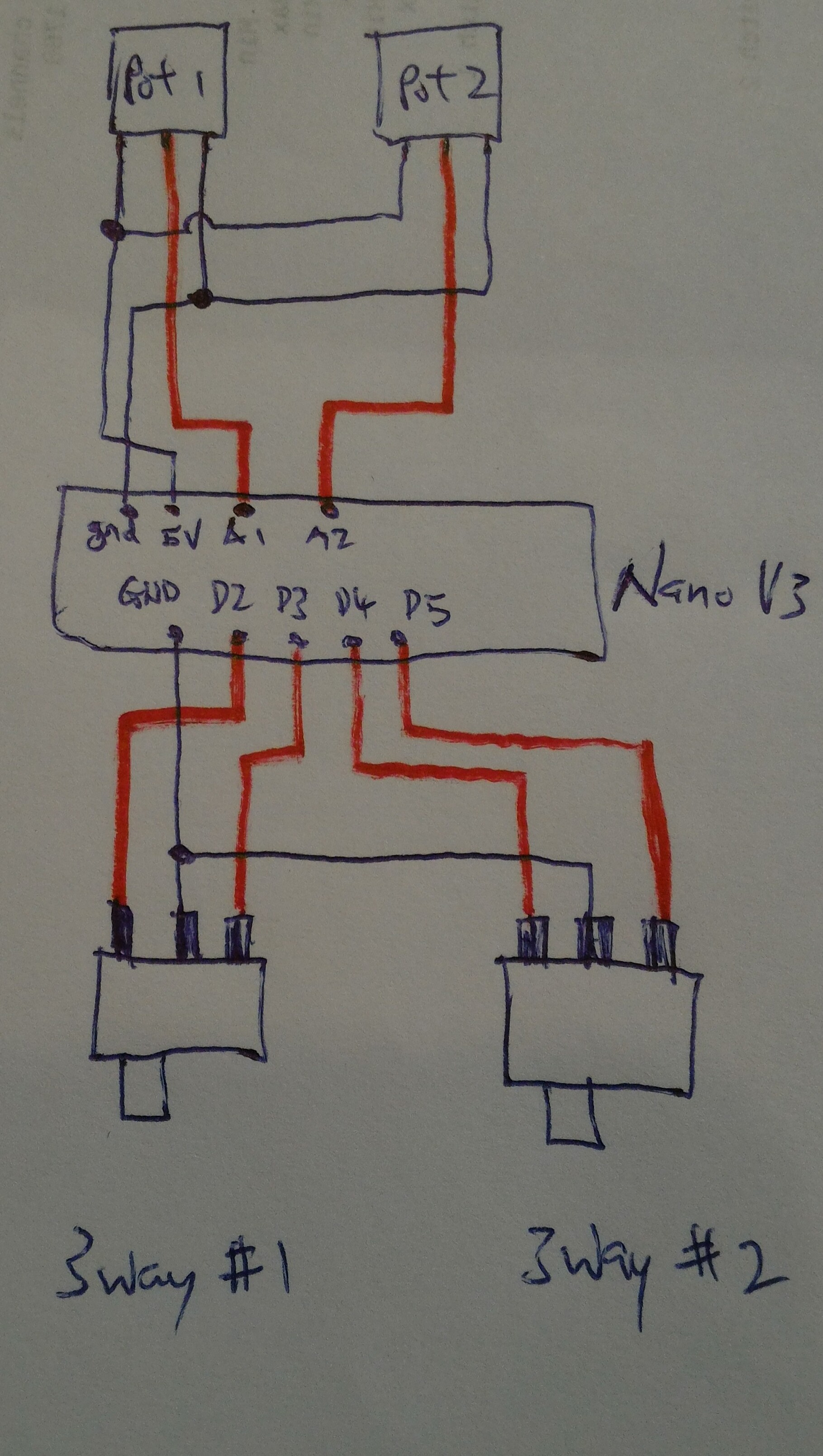
if i read the code correctly :
pot 1 ---- A1 & 5v & GND
pot2 ----A2 & 5v & GND
3way#1 ---- D2 & D3 & GND
3way#2 ----D4 & D5 & GND
ppm out ---- D10
is the connect correct??
Replied by davidwyl on topic Extra inputs for Devo Tx's
Epyon wrote: You can strip out a lot of Ian's original code, such as the dual rate stuff. Having inputs, especially analogs, active with no input can sometimes make everything go wonky.
For 2 pots and 2 3-ways, here's about all you'll need.// Devo 7e PPM input // For use with Arduino Nano V3.0 // Based on sketch by Ian Johnston // Analog pin assignments int AI_Pin_A1 = 2; // potentiometer #1 pin int AI_Pin_A2 = 3; // potentiometer #2 pin int AI_Raw_A1; // Analog In raw var - 0->1023.... int AI_Raw_A2; int A1_uS = 750; // potentiometer #1 us int A2_uS = 750; // potentiometer #2 us int sw1_uS = 750; // 3-way switch #1 us int sw2_uS = 750; // 3-way switch #2 us int Fixed_uS = 300; // PPM frame fixed LOW phase int pulseMin = 750; // pulse minimum width minus start in uS int pulseMax = 1700; // pulse maximum width in uS // Digital pin assignments int outPinPPM = 10; // PPM out int inPinD2 = 2; // 3-way switch #1 pin for position 1. Positions 1 and 3 combine for middle position. int inPinD3 = 3; // 3-way switch #1 pin for position 3 int inPinD4 = 4; // 3-way switch #2 pin for position 1 int inPinD5 = 5; // 3-way switch #2 pin for position 3 ISR(TIMER1_COMPA_vect) { ppmoutput(); // Jump to ppmoutput subroutine } void setup() { pinMode(outPinPPM, OUTPUT); // sets the digital pin as output pinMode(inPinD2, INPUT); // sets the digital pin as input digitalWrite(inPinD2, HIGH); // turn on pull-up resistor pinMode(inPinD3, INPUT); digitalWrite(inPinD3, HIGH); pinMode(inPinD4, INPUT); digitalWrite(inPinD4, HIGH); pinMode(inPinD5, INPUT); digitalWrite(inPinD5, HIGH); // Setup timer TCCR1A = B00110001; // Compare register B used in mode '3' TCCR1B = B00010010; // WGM13 and CS11 set to 1 TCCR1C = B00000000; // All set to 0 TIMSK1 = B00000010; // Interrupt on compare B TIFR1 = B00000010; // Interrupt on compare B OCR1A = 22000; // 22mS PPM output refresh OCR1B = 1000; } void ppmoutput() { // PPM output sub routine // Channel 1 - Analog 1 digitalWrite(outPinPPM, LOW); delayMicroseconds(Fixed_uS); // Hold digitalWrite(outPinPPM, HIGH); delayMicroseconds(A1_uS); // Hold for A1_uS microseconds // Channel 2 - Analog 2 digitalWrite(outPinPPM, LOW); delayMicroseconds(Fixed_uS); // Hold digitalWrite(outPinPPM, HIGH); delayMicroseconds(A2_uS); // Hold for A2_uS microseconds // Channel 3 - 3-way switch #1 digitalWrite(outPinPPM, LOW); delayMicroseconds(Fixed_uS); // Hold digitalWrite(outPinPPM, HIGH); delayMicroseconds(sw1_uS); // Hold for sw1_uS microseconds // Channel 4 - 3-way switch #2 digitalWrite(outPinPPM, LOW); delayMicroseconds(Fixed_uS); // Hold digitalWrite(outPinPPM, HIGH); delayMicroseconds(sw2_uS); // Hold for sw2_uS microseconds // Synchro pulse digitalWrite(outPinPPM, LOW); delayMicroseconds(Fixed_uS); // Hold digitalWrite(outPinPPM, HIGH); // Start Synchro pulse } void loop() { // Main loop // Read analog pins AI_Raw_A1 = analogRead(AI_Pin_A1); AI_Raw_A2 = analogRead(AI_Pin_A2); // Map analog inputs to PPM rates for each of the channels A1_uS = AI_Raw_A1 + pulseMin; A2_uS = AI_Raw_A2 + pulseMin; // Potentiometer limits if (A1_uS <= 750) A1_uS = 750; // Min if (A1_uS >= 1625) A1_uS = 1625; // Max if (A2_uS <= 750) A2_uS = 750; if (A2_uS >= 1625) A2_uS = 1625; // 3-way switch #1 if (digitalRead(inPinD2) == 0) { sw1_uS = 750; } if ((digitalRead(inPinD2) == 1) && (digitalRead(inPinD3) == 1)) { sw1_uS = 1190; // Center us, may need to adjust this } if (digitalRead(inPinD3) == 0) { sw1_uS = 1625; } // 3-way switch #2 if (digitalRead(inPinD4) == 0) { sw2_uS = 750; } if ((digitalRead(inPinD4) == 1) && (digitalRead(inPinD5) == 1)) { sw2_uS = 1190; // Center us, may need to adjust this } if (digitalRead(inPinD5) == 0) { sw2_uS = 1625; } }
122 lines of code.
thanks a lot @Epyon.
if i read the code correctly :
pot 1 ---- A1 & 5v & GND
pot2 ----A2 & 5v & GND
3way#1 ---- D2 & D3 & GND
3way#2 ----D4 & D5 & GND
ppm out ---- D10
is the connect correct??
Last edit: 09 Sep 2015 05:56 by davidwyl.
- Epyon
-
- Offline
Less
More
- Posts: 57
09 Sep 2015 06:19 - 09 Sep 2015 09:48 #37582
by Epyon
Your pots would connect to A2 & A3 as coded, but you can change it to whatever you want. Just change
int AI_Pin_A1 = 2; // potentiometer #1 pin
int AI_Pin_A2 = 3; // potentiometer #2 pin
to
int AI_Pin_A1 = 1; // potentiometer #1 pin
int AI_Pin_A2 = 2; // potentiometer #2 pin
I wouldn't use pins A4 or A5 in case you want an I2C device down the road.
Also, just for clarity, the Arduino's pins would be A0 through A7 right to left as pictured.
*EDIT
I didn't actually answer your question
Yes, your drawing is correct.
Thinking on it some more, I would hook your pots to pins A6 & A7 since they can only be used as analog.
So
int AI_Pin_A1 = 6; // potentiometer #1 pin
int AI_Pin_A2 = 7; // potentiometer #2 pin
Replied by Epyon on topic Extra inputs for Devo Tx's
davidwyl wrote: thanks a lot @Epyon.
if i read the code correctly :
pot 1 ---- A1 & 5v & GND
pot2 ----A2 & 5v & GND
3way#1 ---- D2 & D3 & GND
3way#2 ----D4 & D5 & GND
ppm out ---- D10
is the connect correct??
Your pots would connect to A2 & A3 as coded, but you can change it to whatever you want. Just change
int AI_Pin_A1 = 2; // potentiometer #1 pin
int AI_Pin_A2 = 3; // potentiometer #2 pin
to
int AI_Pin_A1 = 1; // potentiometer #1 pin
int AI_Pin_A2 = 2; // potentiometer #2 pin
I wouldn't use pins A4 or A5 in case you want an I2C device down the road.
Also, just for clarity, the Arduino's pins would be A0 through A7 right to left as pictured.
*EDIT
I didn't actually answer your question
Yes, your drawing is correct.
Thinking on it some more, I would hook your pots to pins A6 & A7 since they can only be used as analog.
So
int AI_Pin_A1 = 6; // potentiometer #1 pin
int AI_Pin_A2 = 7; // potentiometer #2 pin
Last edit: 09 Sep 2015 09:48 by Epyon.
- davidwyl
-
- Offline
Less
More
- Posts: 26
10 Sep 2015 01:42 #37616
by davidwyl
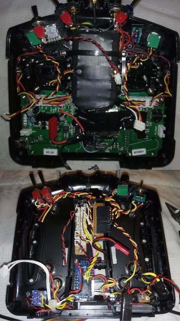
Look at the board while I drow that ugly pic .
.
OK, so I will connect pot to pin 6,7.
Btw, will this code work on arduino mini also Without any modifications?
I got arduino mini & arduino nano, still haven't decide which I will use for my devo 7e.
Replied by davidwyl on topic Extra inputs for Devo Tx's
Ya u r right a0 -a7 is from right to left. Didn't sEpyon wrote: Also, just for clarity, the Arduino's pins would be A0 through A7 right to left as pictured.
*EDIT
I didn't actually answer your question
Yes, your drawing is correct.
Thinking on it some more, I would hook your pots to pins A6 & A7 since they can only be used as analog.
So
int AI_Pin_A1 = 6; // potentiometer #1 pin
int AI_Pin_A2 = 7; // potentiometer #2 pin
Look at the board while I drow that ugly pic
OK, so I will connect pot to pin 6,7.
Btw, will this code work on arduino mini also Without any modifications?
I got arduino mini & arduino nano, still haven't decide which I will use for my devo 7e.
- Deal57
-
- Offline
Less
More
- Posts: 857
10 Sep 2015 03:44 - 10 Sep 2015 03:45 #37618
by Deal57
Deviation Devo7e 3way switch mod, A7105, NRF24L01
Devo6s 2x2 switch mod, trim mod, haptic, multimodule, A7105, NRF24L01, CC2500
Devo12e 4-in-1 with voice mod -- it speaks!!
Replied by Deal57 on topic Extra inputs for Devo Tx's
I used the Arduino Pro Mini. As long as you're doing the software in IDE it should work. These boards do have some slight differences but as long as you match up the right pins and functions, there's nothing that affects what we're doing. Until you get it really loaded up, I guess!
Deviation Devo7e 3way switch mod, A7105, NRF24L01
Devo6s 2x2 switch mod, trim mod, haptic, multimodule, A7105, NRF24L01, CC2500
Devo12e 4-in-1 with voice mod -- it speaks!!
Last edit: 10 Sep 2015 03:45 by Deal57.
- Epyon
-
- Offline
Less
More
- Posts: 57
10 Sep 2015 03:51 #37620
by Epyon
Should work just fine on a Mini. IIRC, the Mini doesn't have pins for A4-A7, just solder pads? Regardless, will work fine.
Replied by Epyon on topic Extra inputs for Devo Tx's
davidwyl wrote: Btw, will this code work on arduino mini also Without any modifications?
I got arduino mini & arduino nano, still haven't decide which I will use for my devo 7e.
Should work just fine on a Mini. IIRC, the Mini doesn't have pins for A4-A7, just solder pads? Regardless, will work fine.
- davidwyl
-
- Offline
Less
More
- Posts: 26
10 Sep 2015 14:56 #37631
by davidwyl
Replied by davidwyl on topic Extra inputs for Devo Tx's
I still playing With my arduino mini & nano.
Will play around with the pot & 3ways Switch soon.
I plan to power arduino from devo 7e main board...Do I need an on/off switch for arduino? Any disadvantage to leave it permanently connected?
(currently I'm using 2s lipo battery to power my devo 7e)
Thanks @deal57 & @epyon for all the help.
Really appreciate it...
- Epyon
-
- Offline
Less
More
- Posts: 57
10 Sep 2015 16:17 #37632
by Epyon
Replied by Epyon on topic Extra inputs for Devo Tx's
davidwyl wrote: I still playing With my arduino mini & nano.
Will play around with the pot & 3ways Switch soon.
I plan to power arduino from devo 7e main board...Do I need an on/off switch for arduino? Any disadvantage to leave it permanently connected?
(currently I'm using 2s lipo battery to power my devo 7e)
Thanks @deal57 & @epyon for all the help.
Really appreciate it...
Epyon wrote: You can get switched 5v from here..........
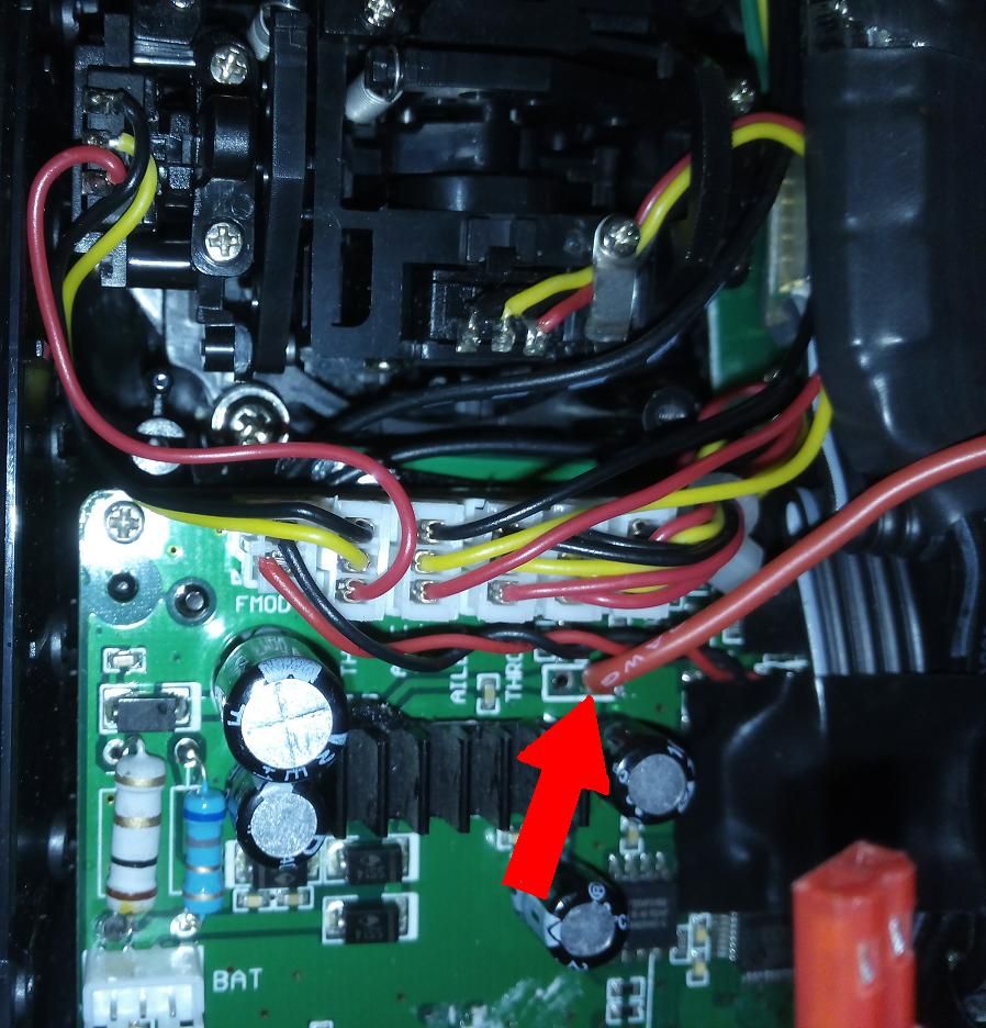
The pad to the left is full battery voltage, so be careful!

- davidwyl
-
- Offline
Less
More
- Posts: 26
11 Sep 2015 00:31 - 11 Sep 2015 00:33 #37649
by davidwyl
Replied by davidwyl on topic Extra inputs for Devo Tx's
Im aware that 5v spot but didn't know the spot next to it is full battery Voltage, thanks for pointing that out.
Is that 5v from devo 7e regulated?
Do I need an on/off switch for arduino? (I won't be using ppm input for certain model that I fly)
Any disadvantage to leave it permanently connected?
Is that 5v from devo 7e regulated?
Do I need an on/off switch for arduino? (I won't be using ppm input for certain model that I fly)
Any disadvantage to leave it permanently connected?
Last edit: 11 Sep 2015 00:33 by davidwyl.
- Epyon
-
- Offline
Less
More
- Posts: 57
11 Sep 2015 06:30 #37651
by Epyon
Replied by Epyon on topic Extra inputs for Devo Tx's
Yep, regulated 5v.
Shouldn't need a switch. You can just disable PPM in certain models.
Only disadvantage would be battery life. I've never worried about that, running a 6500mah LiPo strapped to the back.
Shouldn't need a switch. You can just disable PPM in certain models.
Only disadvantage would be battery life. I've never worried about that, running a 6500mah LiPo strapped to the back.
- davidwyl
-
- Offline
Less
More
- Posts: 26
11 Sep 2015 08:19 #37653
by davidwyl
Replied by davidwyl on topic Extra inputs for Devo Tx's
Connected 3ways switch to arduino, can see it in my devo but the value -109, 0, 109 in stick input menu... Is that ok?
The 3ways Switch added to the devo 7e main board labeled as swA0, swA1, swA2 so I can easily assign the switch to dualrate /complex mode. But 3ways switch added using arduino through ppm only show ppm with -100,0,100 value.
Is it possible to use the 3ways switch from ppm as a dual rate switch?
(For example: position 1- 100%, position 2- 70%,Position 3- 50%)
- Epyon
-
- Offline
Less
More
- Posts: 57
11 Sep 2015 09:15 - 11 Sep 2015 09:29 #37655
by Epyon
That's perfectly fine.
Yes, you'll need to use virtual channels.
OR, since you're only using 4 of the possible 8 PPM channels, you can change the code so the 3-way switches shows up like 6 separate 2-ways.
Replied by Epyon on topic Extra inputs for Devo Tx's
davidwyl wrote: Connected 3ways switch to arduino, can see it in my devo but the value -109, 0, 109 in stick input menu... Is that ok?
That's perfectly fine.
davidwyl wrote: Is it possible to use the 3ways switch from ppm as a dual rate switch?
(For example: position 1- 100%, position 2- 70%,Position 3- 50%)
Yes, you'll need to use virtual channels.
OR, since you're only using 4 of the possible 8 PPM channels, you can change the code so the 3-way switches shows up like 6 separate 2-ways.
// Devo 7e PPM input
// For use with Arduino Nano V3.0
// Based on sketch by Ian Johnston

// Analog pin assignments
int AI_Pin_A1 = 2;    // potentiometer #1 pin
int AI_Pin_A2 = 3;    // potentiometer #2 pin
int AI_Raw_A1;        // Analog In raw var - 0->1023....
int AI_Raw_A2;
int A1_uS = 750;      // potentiometer #1 us
int A2_uS = 750;      // potentiometer #2 us
int sw1_uS = 750;     // 3-way switch #1 position 1 us
int sw2_uS = 750;     // 3-way switch #1 position 2 us
int sw3_uS = 750;     // 3-way switch #1 position 3 us
int sw4_uS = 750;     // 3-way switch #2 position 1 us
int sw5_uS = 750;     // 3-way switch #2 position 2 us
int sw6_uS = 750;     // 3-way switch #2 position 3 us

int Fixed_uS = 300;       // PPM frame fixed LOW phase
int pulseMin = 750;       // pulse minimum width minus start in uS
int pulseMax = 1700;      // pulse maximum width in uS

// Digital pin assignments
int outPinPPM = 10;     // PPM out
int inPinD2 = 2;        // 3-way switch #1 pin for position 1. Positions 1 and 3 combine for middle position.
int inPinD3 = 3;        // 3-way switch #1 pin for position 3
int inPinD4 = 4;        // 3-way switch #2 pin for position 1
int inPinD5 = 5;        // 3-way switch #2 pin for position 3

ISR(TIMER1_COMPA_vect) {
    ppmoutput(); // Jump to ppmoutput subroutine
}

void setup() {

  pinMode(outPinPPM, OUTPUT);   // sets the digital pin as output
  pinMode(inPinD2, INPUT);      // sets the digital pin as input
  digitalWrite(inPinD2, HIGH);  // turn on pull-up resistor
  pinMode(inPinD3, INPUT);
  digitalWrite(inPinD3, HIGH);
  pinMode(inPinD4, INPUT);
  digitalWrite(inPinD4, HIGH);
  pinMode(inPinD5, INPUT);
  digitalWrite(inPinD5, HIGH);

   // Setup timer
  TCCR1A = B00110001; // Compare register B used in mode '3'
  TCCR1B = B00010010; // WGM13 and CS11 set to 1
  TCCR1C = B00000000; // All set to 0
  TIMSK1 = B00000010; // Interrupt on compare B
  TIFR1  = B00000010; // Interrupt on compare B
  OCR1A = 22000; // 22mS PPM output refresh
  OCR1B = 1000;
}

void ppmoutput() { // PPM output sub routine

 // Channel 1 - Analog 1
  digitalWrite(outPinPPM, LOW);
  delayMicroseconds(Fixed_uS);    // Hold
  digitalWrite(outPinPPM, HIGH);
  delayMicroseconds(A1_uS);  // Hold for A1_uS microseconds

 // Channel 2 - Analog 2
  digitalWrite(outPinPPM, LOW);
  delayMicroseconds(Fixed_uS);    // Hold
  digitalWrite(outPinPPM, HIGH);
  delayMicroseconds(A2_uS); // Hold for A2_uS microseconds

// Channel 3 - 3-way switch #1 Position 1
  digitalWrite(outPinPPM, LOW);
  delayMicroseconds(Fixed_uS);    // Hold
  digitalWrite(outPinPPM, HIGH);
  delayMicroseconds(sw1_uS);     // Hold for sw1_uS microseconds

// Channel 4 - 3-way switch #1 Position 2
  digitalWrite(outPinPPM, LOW);
  delayMicroseconds(Fixed_uS);    // Hold
  digitalWrite(outPinPPM, HIGH);
  delayMicroseconds(sw2_uS);     // Hold for sw2_uS microseconds

// Channel 5 - 3-way switch #1 Position 3
  digitalWrite(outPinPPM, LOW);
  delayMicroseconds(Fixed_uS);    // Hold
  digitalWrite(outPinPPM, HIGH);
  delayMicroseconds(sw3_uS);     // Hold for sw3_uS microseconds

// Channel 6 - 3-way switch #2 Position 1
  digitalWrite(outPinPPM, LOW);
  delayMicroseconds(Fixed_uS);    // Hold
  digitalWrite(outPinPPM, HIGH);
  delayMicroseconds(sw4_uS);     // Hold for sw4_uS microseconds

// Channel 7 - 3-way switch #2 Position 2
  digitalWrite(outPinPPM, LOW);
  delayMicroseconds(Fixed_uS);    // Hold
  digitalWrite(outPinPPM, HIGH);
  delayMicroseconds(sw5_uS);     // Hold for sw5_uS microseconds

// Channel 8 - 3-way switch #2 Position 3
  digitalWrite(outPinPPM, LOW);
  delayMicroseconds(Fixed_uS);    // Hold
  digitalWrite(outPinPPM, HIGH);
  delayMicroseconds(sw6_uS);     // Hold for sw6_uS microseconds

// Synchro pulse
  digitalWrite(outPinPPM, LOW);
  delayMicroseconds(Fixed_uS);    // Hold
  digitalWrite(outPinPPM, HIGH);  // Start Synchro pulse
}

void loop() { // Main loop

 // Read analog pins
   AI_Raw_A1 = analogRead(AI_Pin_A1);
   AI_Raw_A2 = analogRead(AI_Pin_A2);

 // Map analog inputs to PPM rates for each of the channels
   A1_uS = AI_Raw_A1 + pulseMin;
   A2_uS = AI_Raw_A2 + pulseMin;

 // Potentiometer limits
  if (A1_uS <= 750) A1_uS = 750;     // Min
  if (A1_uS >= 1625) A1_uS = 1625;   // Max
  if (A2_uS <= 750) A2_uS = 750;
  if (A2_uS >= 1625) A2_uS = 1625;

// 3-way switch #1
  // Position 1
  if (digitalRead(inPinD2) == 0) {
           sw1_uS = 750;
  } else {
           sw1_uS = 1625;
 }
  // Position 2
  if ((digitalRead(inPinD2) == 1) && (digitalRead(inPinD3) == 1)) {
           sw2_uS = 750;
  } else {
           sw2_uS = 1625;
 }
  // Position 3
if (digitalRead(inPinD3) == 0) {
           sw3_uS = 750;
  } else {
           sw3_uS = 1625;
 }

// 3-way switch #2
  // Position 1
  if (digitalRead(inPinD4) == 0) {
           sw4_uS = 750;
  } else {
           sw4_uS = 1625;
 }
  // Position 2
  if ((digitalRead(inPinD4) == 1) && (digitalRead(inPinD5) == 1)) {
           sw5_uS = 750;
  } else {
           sw5_uS = 1625;
 }
  // Position 3
if (digitalRead(inPinD5) == 0) {
           sw6_uS = 750;
  } else {
           sw6_uS = 1625;
 }
}
Last edit: 11 Sep 2015 09:29 by Epyon.
- davidwyl
-
- Offline
Less
More
- Posts: 26
11 Sep 2015 10:20 - 11 Sep 2015 10:21 #37656
by davidwyl
") but i cant seem to compile it.
but i cant seem to compile it.
here is the error i got.
"collect2.exe: error: ld returned 5 exit status
Error compiling."
BTW can u explain how to use virtual channels to use that 3ways switch to control dual rate?
thanks
Replied by davidwyl on topic Extra inputs for Devo Tx's
thanks for the codeEpyon wrote: Yes, you'll need to use virtual channels.
OR, since you're only using 4 of the possible 8 PPM channels, you can change the code so the 3-way switches shows up like 6 separate 2-ways.
here is the error i got.
"collect2.exe: error: ld returned 5 exit status
Error compiling."
BTW can u explain how to use virtual channels to use that 3ways switch to control dual rate?
thanks
Last edit: 11 Sep 2015 10:21 by davidwyl.
Time to create page: 0.380 seconds
-
Home

-
Forum
-
Development
-
Development
- Extra inputs for Devo Tx's