- Posts: 3333
Ultimate Devo F12E (devof12e-XMS) builds
- vlad_vy
-
Topic Author
- Offline
ATTENTION! From 25 Aug 2017 we can use different flash memory chips, from series Microchip SST25VFxxxB and SST25VFxxxA, ISSI IS25CQxxx, Winbond W25QxxBV. Reasonable capacity can be started from 8Mbit. New builds will have name "devof12e-XMS" (Extended Memory Specification).
ATTENTION! From 25 Feb 2018 we can use additional flash memory chips, from series Microchip SST26VFxxxB, Macronix MX25Lxxxxx and Adesto AT25DFxx1A.
ATTENTION! Supported XMS transmitters: Devo F4, Devo F7, Devo F12E, Devo 12s.
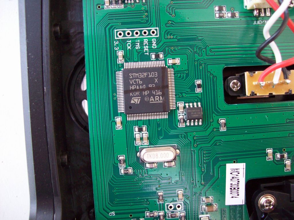
SST25VF032B chip is 2mm wider than UPCT25VF512A, so I need bent pins (about 90 degree to chip surface) in order to fit pins to PCB pads. It takes about a hour to implement the mod. I haven't image of modded Devo F12E board, but you can look on original Devo F12E board:
I've added to my custom v5.0.0 build "devof12e-4MB" and "emu_devof12e-4MB".
If I can to desolder original chip and solder new chip with my old eyes, it can be performed by any user. I use wide chisel (5mm) to desolder (slightly raise) one side of the chip and then do it for other side of the chip. With two iterations I can desolder chip completely.
I do not use any additional pins to solder new chip, I bent pins at right angle to chip surface and solder to PCB tabs.
Unfortunately you can't use original Walkera firmware after this mod.
With my build you have to install "DevoF12E-4MB" firmware exactly same way as for Devo 10: flash firmware by DfuSe USB Upgrade, format USB drive and copy filesystem files.
How to unsolder the chip instruction, from M8A4X.
The used solder is ROHS conform, no lead used. This makes it harder to solder.

Depending on your Tools, the easiest way is to put a lot of new solder on one side of the chips legs, so it touches every single leg on this side. If not all pins are covered you can "wipe" in slow manner over the legs so they warm up even. Then apply some lifting force from the pinless side of the chip and gently! try to lift the heated pins up a bit. The still cold pins on the other chip side will thus bend a little. When you have one side of the legs lifted a little bit it is easy to remove the solder from this side by using solderwick or a desoldering pump or even by the solderingiron alone, always heating the solder, take some away, clean the tip of the iron and again take some solder away until there are no connections to the solderpads.

The other side of the chip goes the same way, but it should get loose pretty fast as it is no longer held in place by the now already loose pinrow on the other chipside.

This way you already apply fresh solder to the pads.

When the chip is removed, go over the solderpads just to get them as "flat" as possible. This helps when installing the new chip.


Pre-tin the legs of the new chip.
Because of the wider new chip body, gently bend its legs closer to its body, check if you bent them enough by placing it over the solderpads. It will be raised a little bit from the mainboard. You could cut the extra length of the pins or leave them as they are. I left them as they are and after installation put some hotglue under the chip to support it a bit. But unless you have the manner to throw your tranmitter on the ground on a regular basis this should not be neccessary as the chip is very lightweight an the soldered pins support it very well.

When the pins fit good, place the new chip on the pads and secure it temporarily with e.g. some tape (you can hold it also in place with some tweezers, if you got a steady hand which I have not...). Now solder one leg of the chip and check if it is still aligned.
If it is ok, solder one pin on the other side of the chip, apply gentle force on top of the chip, the leg should "dip" into the tin on the solderpad.
Once again check the alignment.
If it is OK, solder all the pins to the mainboard by just touching the pin and pad, the applied solder is enough to create the connection in most cases.
Check for solderbridges, if there are some, just heat the spot with the cleaned tip of the iron, normally the solder should find its way to the correct place without bridges.

Good luck!
How to unsolder the chip instruction #2
P.S. If you haven't plans to return back to Walkera firmware and not sure that you can desolder flash memory chip, you can cut chip pins by cutter one by one and then desolder pin remainders one by one. It is much more safe for PCB.Please Log in or Create an account to join the conversation.
- vlad_vy
-
Topic Author
- Offline
- Posts: 3333
File deleted, see below...
Please Log in or Create an account to join the conversation.
- vlad_vy
-
Topic Author
- Offline
- Posts: 3333
Please Log in or Create an account to join the conversation.
- M8A4X
-
- Offline
- M8A4X
- Posts: 103
As soon as they arrive I will give it a try.
Thank you for your effort!
Please Log in or Create an account to join the conversation.
- vlad_vy
-
Topic Author
- Offline
- Posts: 3333
Please Log in or Create an account to join the conversation.
- vlad_vy
-
Topic Author
- Offline
- Posts: 3333
vlad_vy wrote: By the way: dialog boxes at "text" GUI drawn incorrectly. Dialog box borders partially overwritten and so on.
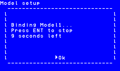
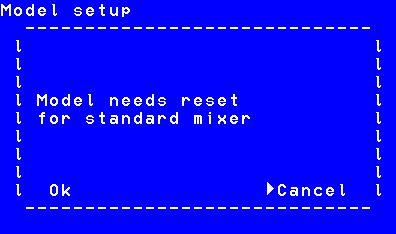
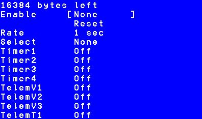
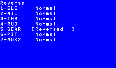
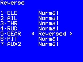
Fixed dialog boxes for "text" GUI. It is "Bind" dialog, "Safety Warning" dialog and change Mixer GUI from "Advanced" to "Standard" dialog. Tested with Devo F12E and Devo F7 emulator.
I will place pull request later.
Please Log in or Create an account to join the conversation.
- Artus
-
- Offline
- Posts: 105
DEVO10 4in1 V5.0 DEVO F12E 4in1 V5
Align TREX 100 (3) Hubsan Q4
Walkera QRW100S Walkera QRX 350 Pro (FPV)
Walkera QRX 350 PREMIUM
DIY 100 mm Micro QUAD - HGLRCF4F5PRO with INAV
Please Log in or Create an account to join the conversation.
- vlad_vy
-
Topic Author
- Offline
- Posts: 3333
Please Log in or Create an account to join the conversation.
- rdowzall
-
- Offline
- Posts: 16
Please Log in or Create an account to join the conversation.
- vlad_vy
-
Topic Author
- Offline
- Posts: 3333
Files deleted, see below...
Please Log in or Create an account to join the conversation.
- FDR
-
- Offline
That would be easier to maintain, and has no limitation unlike the forum...
Please Log in or Create an account to join the conversation.
- vlad_vy
-
Topic Author
- Offline
- Posts: 3333
Please Log in or Create an account to join the conversation.
- vlad_vy
-
Topic Author
- Offline
- Posts: 3333
Please Log in or Create an account to join the conversation.
- vlad_vy
-
Topic Author
- Offline
- Posts: 3333
Please Log in or Create an account to join the conversation.
- vlad_vy
-
Topic Author
- Offline
- Posts: 3333
Please Log in or Create an account to join the conversation.
- vlad_vy
-
Topic Author
- Offline
- Posts: 3333
Files deleted, see below...
Please Log in or Create an account to join the conversation.
- M8A4X
-
- Offline
- M8A4X
- Posts: 103
It is incredible how much and how fast you are doing this code changes!
I remember this "not clearing last charcter" when scrolling through unused models, the letter "E" of "NONE" would remain on the last place of an empty model when the "cursor arrow" has been in front of the line. No big deal but clearly nicer if fixed as if still present!
Thanks a bunch vlad!
Can't wait to get my hands on a replacement Flash chip...
Please Log in or Create an account to join the conversation.
- HappyHarry
-
- Offline
- Posts: 1136
Please Log in or Create an account to join the conversation.
- vlad_vy
-
Topic Author
- Offline
- Posts: 3333
It looks like empty placeholder (window) for model icon and graphs partially overlay Splash dialog and Safety dialog.
Please Log in or Create an account to join the conversation.
- vlad_vy
-
Topic Author
- Offline
- Posts: 3333
Please Log in or Create an account to join the conversation.
-
Home

-
Forum

-
Development

-
Builds

- Ultimate Devo F12E (devof12e-XMS) builds

