- Posts: 983
Ultimate7e tutorial: Four 3-way + two 2-way switch
- Fernandez
-
- Offline
2x 3way and 6x 2way
4x 3Way and 4x 2way
I still have room for two more switches and actually therefore I did not yet wired up yet the extra switches
If not anymore in the pipe, no problem and then will hook up 4x 3 2x 2 as per instruction of thios topic.
Anyway I do not mind to use an extra GPIO pin.
Please Log in or Create an account to join the conversation.
- silpstream
-
Topic Author
- Offline
- Posts: 244
Please Log in or Create an account to join the conversation.
- Fernandez
-
- Offline
- Posts: 983
Was just wondering if this idea was still in the pipe, or that it was decided to stop.
Anyway good to hear
Please Log in or Create an account to join the conversation.
- silpstream
-
Topic Author
- Offline
- Posts: 244
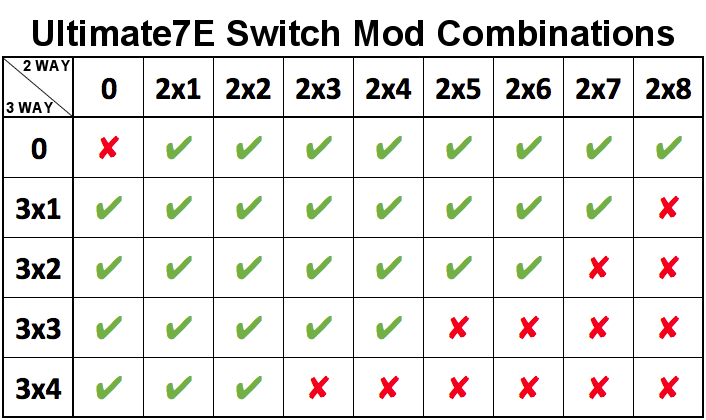
We can now have a maximum of 8 switches (A - H). Possible switch combinations are:
Only the above combinations are supported. Naming convention is number of switch positions x number of switches. Example: 3x2 = 3-way x 2 switches, 2x5 = 2-way x 5 switches.
Configuration for the above is from hardware.ini. The option "extra-switches=nostock" now needs to be added if this mod is used to tell the firmware that the stock HOLD/FMOD switches have been removed. If you are using the previous (original 3x2/3x1/2x2) devo7e switch mod, then do not add the "nostock" option.
My config (new u7e switch mod with 3x4, 2x2, potx2):
extra-switches = nostock
extra-switches = 3x4
extra-switches = 2x2
extra-switches = potx2
Example (original devo7e switch mod with 3x2):
extra-switches = 3x2Given that we now have switches A - H, the 2-way switches have been shifted to ease the conditional logic used. As such, take note that you'll need to update your model.ini files for the new switch names. Basically:
3x4: SWA, SWB, SWC, SWD
3x3: SWA, SWB, SWC
3x2: SWA, SWB
3x1: SWA
2x1: SWH
2x2: SWH, SWG
2x3: SWH, SWG, SWF
2x4: SWH, SWG, SWF, SWE
2x5: SWH, SWG, SWF, SWE, SWD
2x6: SWH, SWG, SWF, SWE, SWD, SWC
2x7: SWH, SWG, SWF, SWE, SWD, SWC, SWB
2x8: SWH, SWG, SWF, SWE, SWD, SWC, SWB, SWAHere's how the wiring should go.
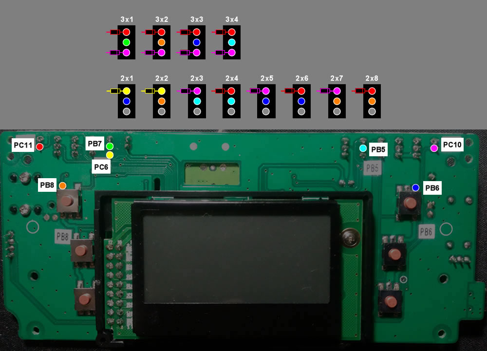
Basically just wire based on the switch config that you want. For example if you are doing 3x4, 2x2, then wire based on 3x1, 3x2, 3x3, 3x4, 2x1, 2x2. If you are doing 3x2, 2x6, then wire based on 3x1, 3x2, 2x1, 2x2, 2x3, 2x4, 2x5, 2x6. Don't forget the diodes as shown.
Please help me test it on both the original switch mod and the u7e switch mod. Thanks guys!
Please Log in or Create an account to join the conversation.
- Fernandez
-
- Offline
- Posts: 983
I always thought.
2x2, means 2pcs a 2 position switch.
2x3, means 2pcs a 3 position switch.
In my ideal case I like to put 3pcs 3way and 3 pcs 2way.
Please Log in or Create an account to join the conversation.
- silpstream
-
Topic Author
- Offline
- Posts: 244
3x2 = 3-way x 2
2x1 = 2-way x 1
In your case you will want 3x3, 2x3.
Please Log in or Create an account to join the conversation.
- Fernandez
-
- Offline
- Posts: 983
4x3 - SWA, SWB, SWC, SWD
4x2 - SWE, SWF, SWG, SWH
Potx2
Take some time, but certainly will do and revert back
Please Log in or Create an account to join the conversation.
- silpstream
-
Topic Author
- Offline
- Posts: 244
Could you also test first with your existing switch mod? I'd like to know if it works for the original switch mod. Thanks!
Please Log in or Create an account to join the conversation.
- Fernandez
-
- Offline
- Posts: 983
It detects pefectly fine my original devo 7e, 4 switches configuration 2x3 and 2x2.
Only thing, it is missing the Frsky X-protocol, which was in previous U7E build.
Please Log in or Create an account to join the conversation.
- silpstream
-
Topic Author
- Offline
- Posts: 244
Please Log in or Create an account to join the conversation.
- Fernandez
-
- Offline
- Posts: 983
in following order:
Left to right: PB6 blue-PB5 light blue-PC10 Pink-PC11 Red -PB7 Green -PC6 Yellow -PB8 Orange
The switch layout seen from back of the Tx, see the image sketch attached.
My hardware.ini looks like this:
;Only useful for transmitters with an after-market vibration motor
;enable-haptic=1
;
;switch_types: 3x4, 3x3, 3x2, 3x1, 2x2, 2x1, potx2, potx1
;May occur more than once if necessary.
extra-switches = nostock
extra-switches = 3x2
extra-switches = 2x4
extra-switches = potx2
;button_types: trim-all, trim-(left|right)-(up|down|both)
;May occur more than once if necessary.
;extra-buttons=
;
;Unique TxId, With tx same id and model bind Id, the rx can be controlled by multiple Tx
;txid = 78968765
;
[modules]
; there is no need to enable the cyrf6936 module unless
; it is wired to an alternate port. It is Enabled automatically otherwise
; enable-cyrf6936 = B12
; has_pa-cyrf6936 = 1
enable-cc2500 = A13
has_pa-cc2500 = 1
enable-a7105 = A14
has_pa-a7105 = 1
enable-nrf24l01 = A15
has_pa-nrf24l01 = 1
; enable-multimod = A13
Anyway there is some response from switches but all is weird I cant put the finger on it, there is something wrong, switches interact sometimes change label depending on other switches etc, sometimes don't work.
I thought I have wired all pretty securely, according your colour drawing, see also photo, but now will first double check it, currently it is not ok.
Please Log in or Create an account to join the conversation.
- silpstream
-
Topic Author
- Offline
- Posts: 244
Also, your hardware.ini should be 2x6 not 2x4.
Hopefully this sorts it out. Again, I'm really sorry for the error.
Please Log in or Create an account to join the conversation.
- Fernandez
-
- Offline
- Posts: 983
But it seem all is wired correct.
It seem there is some bug in the matrix or software?
Ah ok 2x6, but basically the 2 stock switches must be included?
will try check your update.
Please Log in or Create an account to join the conversation.
- silpstream
-
Topic Author
- Offline
- Posts: 244
extra-switches = nostock
extra-switches = 3x2
extra-switches = 2x6
extra-switches = potx2
"nostock" removes the stock switches, so 2x6 defines all the newly wired in switches.
The updated wiring diagram is in post #50865 .
Please Log in or Create an account to join the conversation.
- Fernandez
-
- Offline
- Posts: 983
It is better but there still are problems somewere.
the way I tested it just to flip a switch and check how it is being detected in the display.
2x1 - no detection
2x2 - no detection
2x3 - F0-F1
2x4 - D1-E1
2x5 - C1-D1
2x6 - C0-C1 ok
3x1 - no detection
3x2 - B0-B1-B2 ok
so still some errors in software or matrix
Please Log in or Create an account to join the conversation.
- silpstream
-
Topic Author
- Offline
- Posts: 244
To my horror the diagram I gave you was WRONG a second time. I'm feeling really dumb now, really sorry AGAIN.
I've updated it AGAIN and updated post #50865. Hopefully this is the last time, cause I really checked and rechecked with my TX open and wired for 3x2, 2x6. Here's a video of the result.
Please Log in or Create an account to join the conversation.
- Fernandez
-
- Offline
- Posts: 983
Anyway I can recommend anyone to put a piece of flat cable to the mid of tx, from there you have all connection points from left to right and can easy and neat wire to all switches. It is also relatively simple to change, just shift some wires here length stay same, I did not yet shrink the sleeves.
Will test and let you know.
Please Log in or Create an account to join the conversation.
- Fernandez
-
- Offline
- Posts: 983
I'll check a bit different, just toggle a switch, and then read the swith label in the settings field in a channel.
The current status is:
3x1 - A0-A1-A2
3x2 - B0-B1-B2
2x1 - H0-H1
2x2 - G0-G1
2x3 - E1-D1
2x4 - F0-F1
2x5 - C0-C1
2x6 - D1-C1
The 2x3 and 2x6 are incorrect, switch labels on toggle.
The labels itself seem not correct, would expect 2x1 to be C and 2x2 to be D etc etc.
Please Log in or Create an account to join the conversation.
- silpstream
-
Topic Author
- Offline
- Posts: 244
The 2-way switches go backwards starting from SWH (2x1) anding in SWA(2x8). The 3-way switches go forward from SWA (3x1) to SWD (3x4). They meet in the middle depending on switches configured.
Your 2x3 and 2x4 as well as 2x5 and 2x6 wires for red and pink are reversed so you see them flipped. Don't need to re-solder, just move the switches in the housing.
Please Log in or Create an account to join the conversation.
- Fernandez
-
- Offline
- Posts: 983
I'll make some pictures and short description later, for others want to copy the build 2x3 + 2x6 + 2 pots.
Still I believe might make sence, just to change the labels of switches, so that lower switch label also have the lower letters.
such 3x1 A
3x2 B
2x1 C
2x2 D
2x3 E
etc....
Please Log in or Create an account to join the conversation.


