- Posts: 2
- Forum
- News, Announcements and Feedback
- Feedback & Questions
- Removing shield and diode 7E for better reach
Removing shield and diode 7E for better reach
- apiset
-
- Offline
Please Log in or Create an account to join the conversation.
- FDR
-
- Offline
Please Log in or Create an account to join the conversation.
- drclawscat
-
- Offline
- Posts: 7
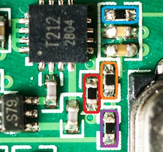
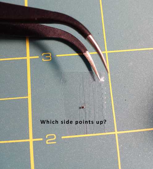
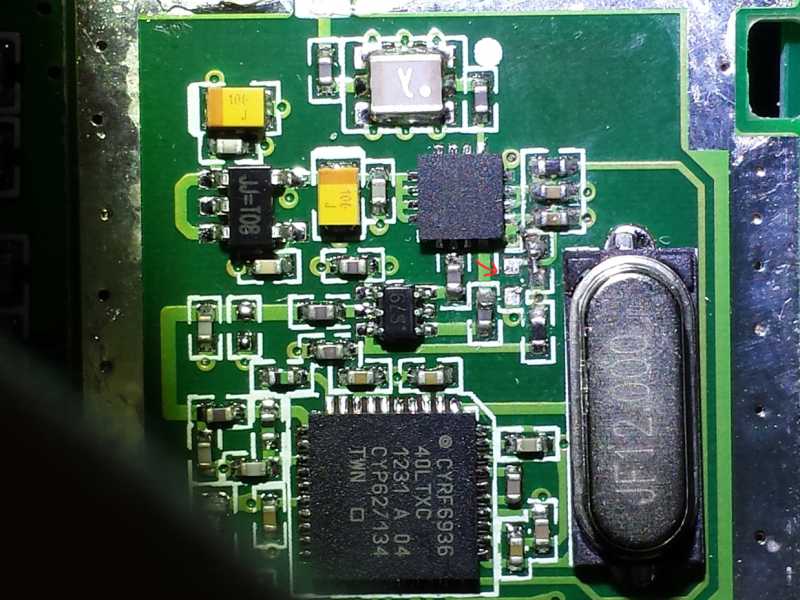
I'm new to the community and trying out this mod. I removed the diode and bridged it with a single strand of copper wire and a tiny bit of solder. However my fat soldering iron tip removed the adjacent 8 o'clock diode as well. I still have it and would like to put it back in but unsure of which end should point north on the board. The diode reads 9.74 on my multimeter with it set at 20k Ohm no matter whether I connect the leads forward or reverse?
I thought diodes should read very differently when reversing the direction of the leads? For confirmation of my multimeter I tested a 3amp 50 PIV diode and it registered totally different values when reversing the leads. I'm far from being an electronics expert so I can't chime in on any of this from experience.
How should I resolder this component? Does it matter which end points which way?
Thanks PB and everyone else for all the hardwork!
Please Log in or Create an account to join the conversation.
- RandMental
-
- Offline
- Posts: 521
drclawscat wrote: my fat soldering iron tip removed the adjacent 8 o'clock diode as well. I still have it and would like to put it back in but unsure of which end should point north on the board.
Which one did you remove accidental?
I need to mod another Devo7e later this week and can then do more measurements to help you.
Please Log in or Create an account to join the conversation.
- drclawscat
-
- Offline
- Posts: 7
I removed the one in Red, also on my picture attached here. May need a bit more solder on the component I'm supposed to bridge as well.
By the way, I removed the RF shield fairly easily using only a 30W soldering iron. The key was using C-FLUX by rectorseal.
www.amazon.com/Rectorseal-74026-3-Ounce-...=8-1&keywords=c-flux
This stuff is amazing, it cleans your solder tips perfectly and also turns any solder into melted butter almost instantly when combined with heat. Just wipe a really small amount on the area you want to melt and hit it with the solder iron.
I started at the bottom left corner of the shield first. I lifted it with a mini flat head in the small square gap by twisting the head back and forth and then levering it while melting the solder. Repeat in the top right corner and you'll have two ends free where you can slide your flathead under the gap you've made in the left and right side of the shield and repeat the same C-Flux solder trick on the remaining two corners.
Please Log in or Create an account to join the conversation.
- RandMental
-
- Offline
- Posts: 521
drclawscat wrote: By the way, I removed the RF shield fairly easily using only a 30W soldering iron. The key was using C-FLUX by rectorseal.
www.amazon.com/Rectorseal-74026-3-Ounce-...=8-1&keywords=c-flux
What you discovered is one of the secrets to soldering both large and very small items - a good quality solder flux makes all the difference. The flux inside the solder wire is normally sufficient for tinting wires and soldering through-hole components on a PCB, but for SMD and these type of work solder flux and/or solder paste are critical.
Give me a few days, I'll come back to you.
Please Log in or Create an account to join the conversation.
- drclawscat
-
- Offline
- Posts: 7
C-Flux is really some amazing stuff, I had a solder tip that was completely black and burnt and dipping it in there a few times while wiping with an Auyoe brass wire soler tip cleaner had it sparkling silver again.
Btw I measured the resistance across the diode we are supposed to be removing for full range. It measured 9.88 in either test lead direction at 20K Ohm setting. Perhaps when you have the chance you can try in-circuit measurement of both to confirm current flow direction/resistance of the 'range removal' diode as well as the one I removed in red?
What type of solder tips are you all using for the diode removal? I used a standard pointed tip, and even with 10x magnification it was like a sledgehammer trying to do surgery.
Please Log in or Create an account to join the conversation.
- quique65
-
- Offline
- Posts: 45
I don't have the skills and tools to do the diode mod but I have a spare 8S/12S RF Module.
Can I install the module as an external one and enable it (disabling the original) using the Deviation firmware?. If it's possible, which version of Deviation should I use and which configuration file I need to modify?.
Thanks is advance for your help.
Regards.
Please Log in or Create an account to join the conversation.
- RandMental
-
- Offline
- Posts: 521
drclawscat wrote: What type of solder tips are you all using for the diode removal? I used a standard pointed tip, and even with 10x magnification it was like a sledgehammer trying to do surgery.
Best would be a tip as fine as you can get, if you have an older tip see if you can file it down a bit to have a sharp point. Be careful though as you might file through the outer sleeve, exposing the inner softer copper alloy they use for good heat transfer. That will oxidize and erode very quickly.
Personally I have a few needle point tips for SMD touch-up work, but for this I am lucky to have SMD hot air workstation at home and after applying a bit of flux/paste, you just lift the diode off with fine point tweezers before adding solder to short the two pads.
Please Log in or Create an account to join the conversation.
- RandMental
-
- Offline
- Posts: 521
quique65 wrote: Hello.
I don't have the skills and tools to do the diode mod but I have a spare 8S/12S RF Module.
Can I install the module as an external one and enable it (disabling the original) using the Deviation firmware?. If it's possible, which version of Deviation should I use and which configuration file I need to modify?.
Thanks is advance for your help.
Regards.
This is indeed possible to add it as an additional module. Using the tx.ini file you can tell Deviation to use the new module rather than the old when selecting the CYRF based protocols..
I cannot remember seeing a wiring diagram for this, but you can work it out from the Module table in the Module Installation manual.
Please Log in or Create an account to join the conversation.
- quique65
-
- Offline
- Posts: 45
Please Log in or Create an account to join the conversation.
- drclawscat
-
- Offline
- Posts: 7
I know the feature works because when I measured a 3amp 50PIV diode I get a 500 reading on the DMM and 1 in the other direction.
Also I don't think these micro smd components are shorted because I still get a Ohm reading from them.
Please Log in or Create an account to join the conversation.
- RandMental
-
- Offline
- Posts: 521
Please Log in or Create an account to join the conversation.
- drclawscat
-
- Offline
- Posts: 7
Please Log in or Create an account to join the conversation.
- SeByDocKy
-
- Offline
- Posts: 1016
But immediatly, it seems for me hard to remove/unsolder the RF shield ...
Any advices ?
Please Log in or Create an account to join the conversation.
- drclawscat
-
- Offline
- Posts: 7
Be patient with the diode mod as it is really tiny soldering, as you can see I underestimated this! You can wrap some solid strand copper wire around your solder tip and fashion a small tail from the end. Sharpen it with an exacto blade and then tin it with flux to get a temporary tip fine enough for smd soldering.
Please Log in or Create an account to join the conversation.
- SeByDocKy
-
- Offline
- Posts: 1016
drclawscat wrote: Hi SBD, refer to my post #12775 for details on how to remove the shield. You need to swab on a good paste style flux to the existing solder points on the shield to promote melting. Also I used a solder sucker to reduce the amount of solder on each joint. Took about 7-10 plunges per corner while being conservative. You can get one on BG or DX for around 3 dollars if you don't have one in your tool kit. A desoldering braid might be a bit faster and just as economical.
Be patient with the diode mod as it is really tiny soldering, as you can see I underestimated this! You can wrap some solid strand copper wire around your solder tip and fashion a small tail from the end. Sharpen it with an exacto blade and then tin it with flux to get a temporary tip fine enough for smd soldering.
Hi,
I got already a solder sucker pump... Ok I will go slower if I understantd between 8 to 10 pumping per coner ... I see
Nice trick to tweet a copper wire to have a second finer tip
Thank you
Please Log in or Create an account to join the conversation.
- drclawscat
-
- Offline
- Posts: 7
soldering iron fingers are itching. Just received a fine tip butane torch soldering iron from Santa banggood this week. I'm going to cover the board with poster putty to protect any 'unwanted' 'undesirable' soldering action on my next go, once the good folks here figure on what needs a doing.
Please Log in or Create an account to join the conversation.
- MassiveOverkill
-
- Offline
- Posts: 49
Please Log in or Create an account to join the conversation.
- Dante1
-
- Offline
- Posts: 15
Thanks
Please Log in or Create an account to join the conversation.
- Forum
- News, Announcements and Feedback
- Feedback & Questions
- Removing shield and diode 7E for better reach
-
Home

-
Forum

-
News, Announcements and Feedback

-
Feedback & Questions

- Removing shield and diode 7E for better reach


