- Posts: 1433
- Forum
- News, Announcements and Feedback
- Feedback & Questions
- Removing shield and diode 7E for better reach
Removing shield and diode 7E for better reach
- rbe2012
-
- Offline
- So much to do, so little time...
"Default" means in this case that you don't have options to change the value. The rf module should be disabled when using PPM or USB HID.Jman841 wrote: When using my Sim heli load, the output on it is PPM, however, the power output is "Default" which is 150 mW.
Please Log in or Create an account to join the conversation.
- Jman841
-
- Offline
- Posts: 45
robca wrote:
Jman841 wrote: 3. Remove the diode carefully! i tapped it extremely quickly and gently with pressure on the diode with a tooth pick until it was enough to move, then used the tooth pick to fling the diode off. if you slip even a mm you are going to hit a different diode and desolder it (this has happened to many people.)
A bit too late for youbut might be helpful to others.
Actually there is no need to remove the diode. A short is a short, no matter if there is a diode underneath or not. The best past of the "conductive ink" mod, is that it's very low risk: just paint over the diode, no need to get a soldering iron near any of the components (beyond removing the shield: a solder sucker tool is your friend for that)
And I don't see why anyone would want to do that, but the conductive ink mod can also be reversed by scraping away the paint.
I tried this first, Everyone keeps reminding me of this. I did try it with just the conductive ink before I went ahead and removed the Diode.
The issue was it did not work. This has been reported by other people as well, not sure exactly why, but it did not successfully short the diode. Only after I removed the Diode did this mod work with the conductive ink.
If you use a wire and solder around the Diode that can work, but I did not have any success using conductive ink alone. Diode had to be removed.
Please Log in or Create an account to join the conversation.
- robca
-
- Offline
- Posts: 174
For people trying the conductive ink first, I would use a small cotton bud with water and/or rubbing alcohol, to remove the flux and provide a clean surface for the ink to make a good contact
I saw the pictures of the wire HappyHarry soldered, but those are mad soldering skills
I tried soldering over the diode, btw, but the surface tension from the solder tin itself made the diode stick to the soldering tip, and the diode was gone
Please Log in or Create an account to join the conversation.
- Jman841
-
- Offline
- Posts: 45
Is anyone here flying a 450 class heli with the Devo 7e? Or should I look at having to purchase a full sized tx.
I love the size of this thing and will add some additional switches soon as well.
Please Log in or Create an account to join the conversation.
- suzali
-
- Offline
- Posts: 37
Tried different Tx power settings. According to the manual nothing should change on a Devo7e. Should always display 150mw due to software configuration.
On mine I can see all the changes from 0.1 up to 150 mW. (Sorry, can't measure that)
I am wondering, if Walkera has changed some hardware? I have a brand new Devo7e direcly imported from China.
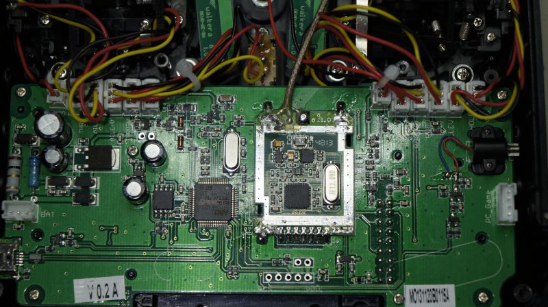
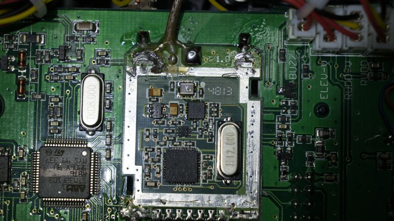
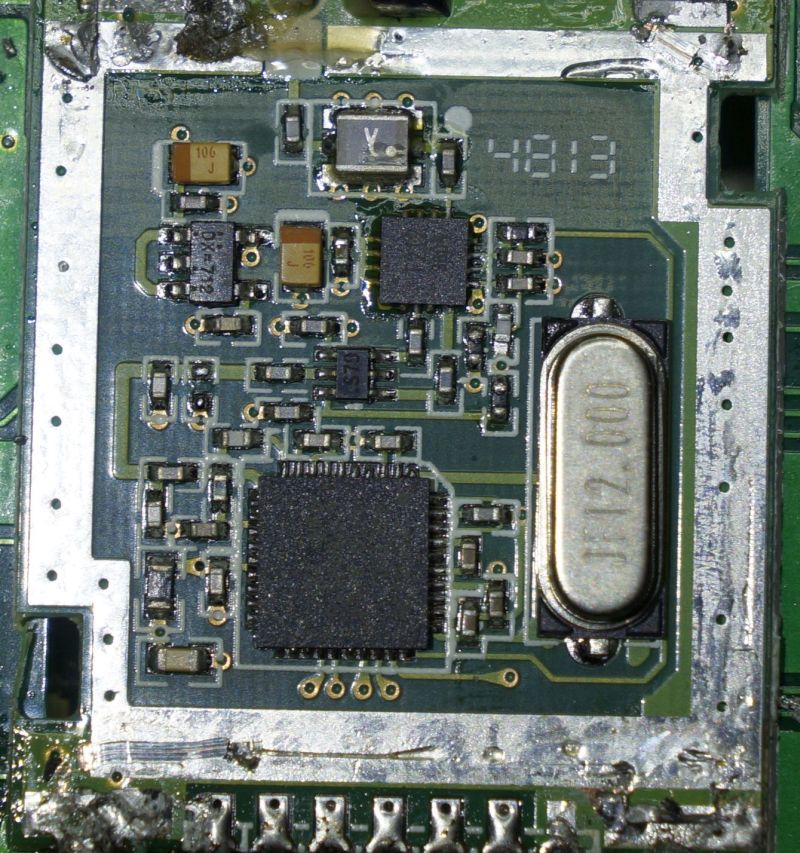
Comparing the pictures showing the diode removal there are a few slight
differences. In main the black diode is white on my board:
Please Log in or Create an account to join the conversation.
- victzh
-
- Offline
- Posts: 1386
Please Log in or Create an account to join the conversation.
- suzali
-
- Offline
- Posts: 37
I measured 18 kohm in both directions... But no guarantee on that, my measuring tips are too large
Please Log in or Create an account to join the conversation.
- Jman841
-
- Offline
- Posts: 45
Has anyone actually range tested the mod yet? Before the mod I got about 100m range with this Tx. if this is a 10x power increase, what type of distances should we be expecting?
I am no expert in signals, but a 10x power increase does not mean a 10x distance increase. In theory what should the new range be? and in reality what is the practical distance increases?
Please Log in or Create an account to join the conversation.
- SeByDocKy
-
- Offline
- Posts: 1016
Jman841 wrote: Hmm interesting. Mine is only about 2 months old and didnt have a white diode.
Has anyone actually range tested the mod yet? Before the mod I got about 100m range with this Tx. if this is a 10x power increase, what type of distances should we be expecting?
I am no expert in signals, but a 10x power increase does not mean a 10x distance increase. In theory what should the new range be? and in reality what is the practical distance increases?
The power loss is quadradic versus distance .... so you will have sqrt(10) at max.
Please Log in or Create an account to join the conversation.
- Jman841
-
- Offline
- Posts: 45
So safe distance is about 350m?
Please Log in or Create an account to join the conversation.
- Jman841
-
- Offline
- Posts: 45
Not bad but Definitely not good.
Please Log in or Create an account to join the conversation.
- SeByDocKy
-
- Offline
- Posts: 1016
Jman841 wrote: Oh wait, sorry, I shouldnt add the original distance. Total distance should be around 316m. Safe distance around 250m.
Not bad but Definitely not good.
correct
Please Log in or Create an account to join the conversation.
- HappyHarry
-
- Offline
- Posts: 1136
Please Log in or Create an account to join the conversation.
- Jman841
-
- Offline
- Posts: 45
HappyHarry wrote: well i've flown my fw190 more than 400m out with no issues on dsm2 with my range modded 7e so i'd reckon that the range is a good bit more than 300m
Awesome! next time I have a large field I will pace count it out with my MCPX BL.
that makes me feel alittle safer. Currently building a Gaui X3 and plan to use this Tx till i can get a better one. 400m is plenty safe for a 450 class.
the 100m was short and ground distance on original estimate. Most likely Air distance with direct LOS is more more like 150m. If i do the equation for 150m it puts it at 474m max distance. call it 400 to be safe.
Please Log in or Create an account to join the conversation.
- Jman841
-
- Offline
- Posts: 45
at 100uM was able to stay bound to a MCPX BL at 20 feet. Just a note, the antenna on the MCPX BL is wrapped around the frame which is just mind boggling that they designed it that way, I unwrapped it and oriented it properly for this range. With the wrapped antenna, range at 100 uM was about 3 feet.
Please Log in or Create an account to join the conversation.
- MicSmitty
-
- Offline
- Posts: 9
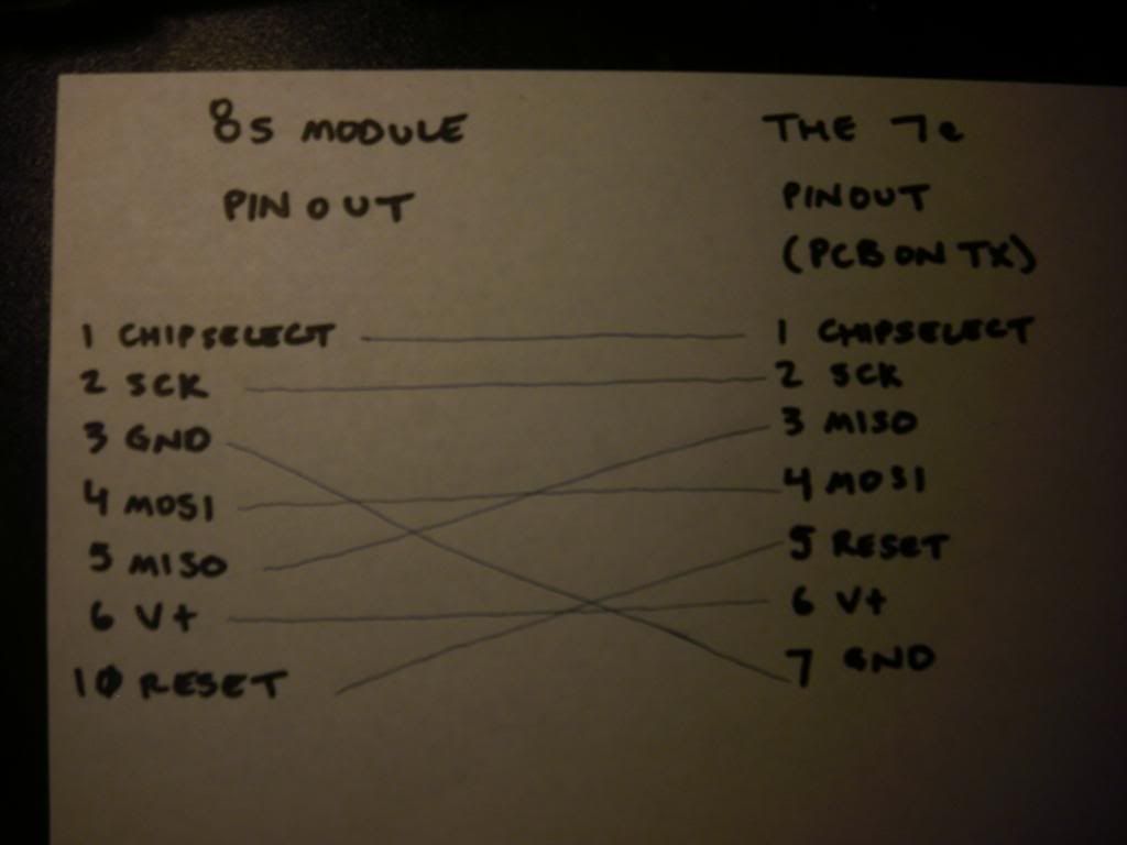
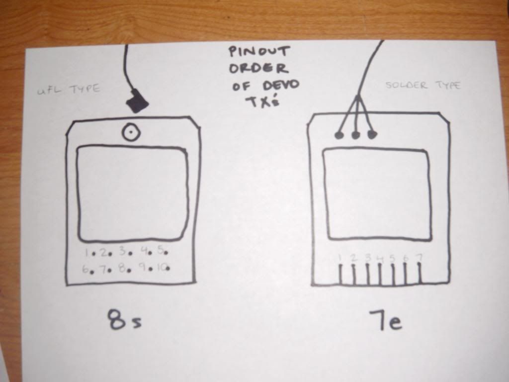
Since the 8s module sits ontop of the 7e's PCB and the pinouts don't line up perfectly, how do you install it? Use wires and secure 8s module somewhere else?
To help others in installing a 8s module in a 7e transmitter (and so others understand what I'm asking) below in the attachment pic is the pinout I found in another thread by PB. I just wrote it differently to show how you can't place the 8s module directly on the 7e PCB like it was...
Also, what happens to the 8s module pinouts 7,8, and 9? Don't use them?
Again, thanks to all for this project/forum/user materials.
Please Log in or Create an account to join the conversation.
- MicSmitty
-
- Offline
- Posts: 9
1. After removing 7e module, you'll want to put the 8s in the same area. You'll use wires to make the correct connections since the pins no longer line up from the 8s module to the 7e board.
2. The 8s module uses the uFL type connection to attach the antenna. Notice the antenna off your 7e solders on--you can't reuse this antenna easily if at all. Good thing is the uFL connection is popular. So, buy a 2 dbi (or close to 2 dbi antenna with this type of connector on one end). There are various places to acquire these. Not sure if you could make it fit but as an example--the Spektrum DX6i replacement antenna would work.


Please Log in or Create an account to join the conversation.
- suzali
-
- Offline
- Posts: 37
Please Log in or Create an account to join the conversation.
- MicSmitty
-
- Offline
- Posts: 9
hobbyone.com.hk/
FYI, I'll do a whole pic by pic thing for others if it's needed to do this. (Like if I run into some special little things for it to work well). I understand how even the easiest of things can be or seem complicated when your new. (I am too when it comes to "component level stuff" other than a backlight mod on a dx6i, lol). I've only worked on 1:1 jets at the organizational level prior--so ya--good luck and wish me some too.
Please Log in or Create an account to join the conversation.
- suzali
-
- Offline
- Posts: 37
looking forward to your pic by pic thing!
Please Log in or Create an account to join the conversation.
- Forum
- News, Announcements and Feedback
- Feedback & Questions
- Removing shield and diode 7E for better reach
-
Home

-
Forum

-
News, Announcements and Feedback

-
Feedback & Questions

- Removing shield and diode 7E for better reach

