Deviation for Devo F4?
- SirDomsen
-
- Offline
Please Log in or Create an account to join the conversation.
- Epitaph
-
Topic Author
- Offline
- Posts: 291
Now you can get back to having some fun!!
Please Log in or Create an account to join the conversation.
- Epitaph
-
Topic Author
- Offline
- Posts: 291
Anyway, I had a brainstorm, but I would need someone to help me with a tiny thing. I wanted to have the throttle trim as a throttle trim, and have some button somewhere to turn the video on and off instead. The problem is I can't figure out (and never have been able to figure out) how to move the control from the trim to one of the switches, for example, to the FMODE switch. Every time I've tried, it just won't do what I want it to do.
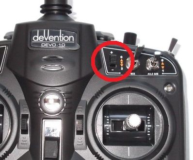
The brainstorm I have... I have my transmitter looking very much like an F7 right now switchwise, with the exception of the TRN/HOLD switch which is where I have my video antenna... anyway, getting back to it. I don't need any more switches for my uses, what I have now is perfect for my needs (once I get the dial sorted), and I like to have things look original or at the very least smart. So I was wondering where to put the video switch... and if I can figure out another switch on the MCU for a simple on/off switch, then what I am going to do is fit a small on/off switch where the Devo 10 has its dial trims, as the F4 (and the F7) has the plastic inside molded for it!!
It'll be a perfect little switch to turn the video on and off, and it's not something I'm going to flick by mistake in flight because of how small it is. I have the switch already, as I have an old Walkera WK-2402 transmitter for parts, and the power switch on it is perfect!! So I can have a nice switch that looks original, and be functional.
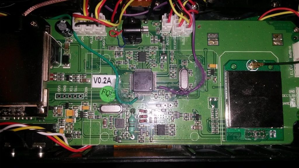
Now, writing this I have a theory as to why I couldn't get the HOLD switch to work... there are 2 pins marked as HOLD, one of which has an asterisk. The switch is shared along with the TRN switch... so, what about if HOLD is not from the MCU to GND, but rather those 2 pins bridged... and TRN is one of those HOLD pins bridged with the TRN one? If so, would they bridge direct or via a resistor or something? Also, what does the asterisk mean?? I mean, I was thinking about using the GEAR switch for my video switch (video gear, it fits I guess hehehe), but GEAR also has an asterisk. D/R and the 2 MIX pins also have an asterisk, but FMODE doesn't. I'm wondering if an asterisk means that they don't connect to GND, but to another pin... and if it is the case, then which one to which? I mean, if it were the HOLD pin without the asterisk for all of them, why call it HOLD?
I'm going to have to do some testing... if the worst comes to the worst and I can't figure out another switch, then I'll put VIDEO onto FMODE, rewire that into the new switch, and put the existing FMODE switch via the arduino.
BTW... does anyone have an F7 to at least tell me what input name on Deviation is controlled by the dial? It's marked as AUX2, but there is no AUX2 in the Deviation list of switches to change.
Please Log in or Create an account to join the conversation.
- SirDomsen
-
- Offline
Assigning a switch for video on/off is easy. go to model setup-->video. There you can,select the channel,and the switch for on off. Note: better do this,with a vtx enabled, because if you select video and assign it to a switch that is not installed, you will stuck in,video mode. e.g. the bluescreen without menu.
To get back the trim switch to,work, go to trim and set it up the same way as on,ail for example (but use thr instead of ail obviously)
Please Log in or Create an account to join the conversation.
- Epitaph
-
Topic Author
- Offline
- Posts: 291
Thanks, takes a moment to get it right but I got it working on the FMODE channel... and I can find GEAR1 on the selection available... so if I can find that switch and get it working, should work great!!
Shame I can't figure out the pot pin, that would have been perfect... seems a waste to have to add an arduino for just one pot, but I don't need more than one
Please Log in or Create an account to join the conversation.
- Epitaph
-
Topic Author
- Offline
- Posts: 291
I can now confirm that this point here on this image (3rd pin from the bottom, the wire is so fine it didn't come out in the photo) is for the GEAR switch, and it just goes to ground like the FMODE switch does. Supposedly, the D/R switch is right above it (4th pin from the bottom), but I haven't tried it yet, nor do I know what it would change as there is no "D/R" in the input monitor. Those that don't want to add a switch like this might find this point useful to use the GEAR switch in place of a HOLD switch for their throttle... I'm going to try and find one more switch later on to see if I can get that as a programmable switch, as my mod is fine for planes and multirotors, but not good for 6ch helis that need HOLD in the centre of the stick.
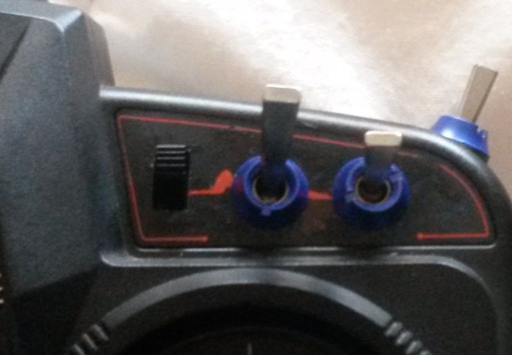
I think the switch has come out pretty good, and looks very luch like the pot trim switch on the Devo 10
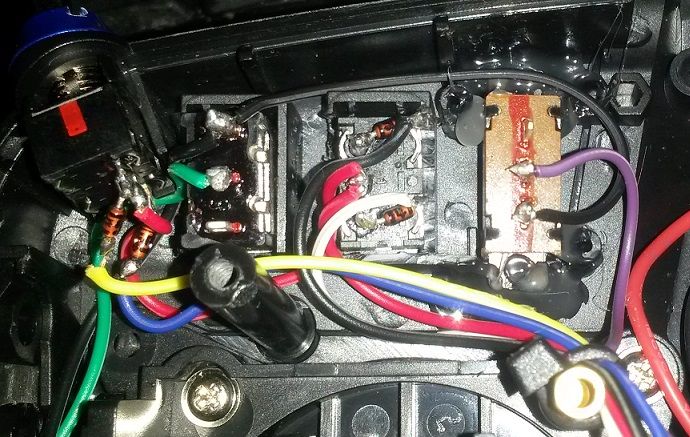
And on the inside, just glued in carefully with hot glue, being careful not to glue the actual switch as the switch is open on the ends, and you can get glue inside... but it came out great I think!! As I said, it just directs the pin from the MCU direct to ground, which here I just wired it into the ground of the FMODE switch
As far as working os concerned, it works great!! In the up position, the screen in is "menu mode", and in the down position, it's in "FPV mode". It protrudes enough to be able to flick it easily, but low enough in comparison with the other 2 switches up there to not be knocked by mistake in flight... you have to consciously turn it on and off, which is just what I was looking for, and aesthetically fits in just right with the rest of the transmitter I think.
Thank you Sir for clarifying that with the video switch, I now have one model base which I will use as a template, so they all have video on/off from the initial creation.
Please Log in or Create an account to join the conversation.
- Buoncristiani
-
- Offline
- Posts: 7
Thank you all
Please Log in or Create an account to join the conversation.
- Epitaph
-
Topic Author
- Offline
- Posts: 291
If not, copy it in...
Please Log in or Create an account to join the conversation.
- PhracturedBlue
-
- Offline
- Posts: 4403
Please Log in or Create an account to join the conversation.
- Epitaph
-
Topic Author
- Offline
- Posts: 291
Please Log in or Create an account to join the conversation.
- SirDomsen
-
- Offline
Please Log in or Create an account to join the conversation.
- Arnold
-
- Offline
- Posts: 304
PhracturedBlue wrote: ... If you are on a Mac, this is known not to work, and you'll need to find some alternative
For me the alternative is to use the buildfs tool to create the devo.fs file directly on the controller. And since you'll be using that tool anyway to make changes to the contents of the radio, it may as well be the last step in the process, in my opinion.
<Edit> Thanks SirDomsen & Epitaph!
Too many hobbies & too many Devos!
Who knows where the time goes?
Please Log in or Create an account to join the conversation.
- PhracturedBlue
-
- Offline
- Posts: 4403
That is a good solution. I need to update the manual with instructions for the F* series sooner or later. For now I added a new wiki page.Arnold wrote:
PhracturedBlue wrote: ... If you are on a Mac, this is known not to work, and you'll need to find some alternative
For me the alternative is to use the builds tool to create the devo.fs file directly on the controller. And since you'll be using that tool anyway to make changes to the contents of the radio, it may as well be the last step in the process, in my opinion.
<Edit> Thanks SirDomsen & Epitaph!
www.deviationtx.com/wiki/installing_on_f_series
If you see any issues, let me know (or even better just fix them, the wiki is open to all users)
Please Log in or Create an account to join the conversation.
- Arnold
-
- Offline
- Posts: 304
PhracturedBlue wrote: ... If you see any issues, let me know (or even better just fix them, the wiki is open to all users)
Nice! I fixed a couple of minor typos, but ...
I question this:
After following the typical installation (using the DfuSe tool, or Deviation Uploader to install the dfu file), rebooting the transmitter should result in a screen that says 'Deviation USB'I guess I should let you decide what you want to say about that.
I could copy the info from the Wiki to the manual, but I don't think I'm competent working with markup and this calls for section headings.
Too many hobbies & too many Devos!
Who knows where the time goes?
Please Log in or Create an account to join the conversation.
- PhracturedBlue
-
- Offline
- Posts: 4403
Arnold wrote:
PhracturedBlue wrote: ... If you see any issues, let me know (or even better just fix them, the wiki is open to all users)
Nice! I fixed a couple of minor typos, but ...
I question this:At this point the Deviaton Uploader Tool 0.8.0 does not recognize the F4 - don't know about the others in the F series.We need to use the special version of the Uploader that you created (Thank You!).After following the typical installation (using the DfuSe tool, or Deviation Uploader to install the dfu file), rebooting the transmitter should result in a screen that says 'Deviation USB'
I guess I should let you decide what you want to say about that.
I could copy the info from the Wiki to the manual, but I don't think I'm competent working with markup and this calls for section headings.
I tweaked the wording a little. At some point I'll merge the fixes I made for the F7/F4 into the trunk so that Deviation Uploader can work for you
Please Log in or Create an account to join the conversation.
- Epitaph
-
Topic Author
- Offline
- Posts: 291
That said, are you going to add F4 to the "Welcome to Deviation" initial home page list or are you going to wait till the major bugs are ironed out?
Please Log in or Create an account to join the conversation.
- Epitaph
-
Topic Author
- Offline
- Posts: 291
But one thing I was wondering, I haven't had the chance to try them out yet so i don't know, but is there a way to get the telemetry overlay on the video feed? I mean, if there isn't a way or it can't be added because of limitations, then there isn't... but if you can, it would be good for things like battery voltage and things like that.
Please Log in or Create an account to join the conversation.
- Epitaph
-
Topic Author
- Offline
- Posts: 291
I'm feeding the Arduino exactly 5V in via the Vcc in pin (not the USB port), and the pots get their Vcc and GND off the existing transmitter pots (which is something like 3.6V). I found that feeding the Arduino directly from the battery gave a fluctuating value to the PPM values depending on the charge of the battery, hence why I fed it off a UBEC to have a constant value. I tried with the pots getting their Vcc off the UBEC too, but that was giving me even more wackier results on the centre and the end points.
I mean, it's working now and going great as long as I remember those values in the setup when i configure a model, but I was just curious as to what sketch you ended up using.
Please Log in or Create an account to join the conversation.
- PhracturedBlue
-
- Offline
- Posts: 4403
I haven't really played with the F7 much. But I believe the overlay works ok as long as you have a video feed available. So if you are in no-video mode, you see the text, if you are in video mode and video is being transmitted you see the text, if you are in video mode and no video is being transmitted, you see nothing.Epitaph wrote: But one thing I was wondering, I haven't had the chance to try them out yet so i don't know, but is there a way to get the telemetry overlay on the video feed? I mean, if there isn't a way or it can't be added because of limitations, then there isn't... but if you can, it would be good for things like battery voltage and things like that.
This appears to either be a limitation of the F4/F7 or a configuration issue of the display that I can't figure out. The F12e uses a different display and properly displays the overlay regardless of video status.
Please Log in or Create an account to join the conversation.
- SirDomsen
-
- Offline
I'm feeding the arduino with 3.3V from Devo's stock 3.3V supply - works great, as the Arduinos I use run very stable at that voltage (Pro mini somewhere from Aliexpress, black PCB)
@PB I have an assumption what happens while in Video mode: If you fly FPV (which works great with your devo.fs improvements you mentioned!) and reach the end of transmitting range, some noise gets into the display. The noise seems to "blow" the OSD away. If the picture gets really bad, almost everything of the OSD is gone. When signal is lost, The F4 overlays that blue screen. If you use the video out, you can see the noise it still receives - but the OSD cant be seen on noisy background. I suppose that we should have an algorithm here that switches video off if no video signal is received anymore - perhaps when the Devo starts dispaying its blue screen, if there is any chance to get that for Deviation. that would also prevent us from a weird thing: If you want to select the switch for video on/off, you always have to connect a working vTX, because video mode gets activated once you want to select Video switch and you will likely stuck in that blue screen then and can't see what you are doing in the menus anymore. It's difficult to select the correct video switch then
Please Log in or Create an account to join the conversation.
-
Home

-
Forum

-
Development

-
Development

- Deviation for Devo F4?


