Wishlist for a custom Transmitter board
- robocog
-
- Offline
So when you say not for Devo7E µcu....Do you mean just not on a std 7e?
I already have an SSD1306 in another project and willing to pull it for testing to destruction as soon as the boards arrive
I can get hold of another SSD1306 inexpensively, locally too so not a problem if things don't work out and the 'borrowed' one becomes a sacrifice to testing
Regards
Rob
Please Log in or Create an account to join the conversation.
- compman2
-
- Offline
- Posts: 65
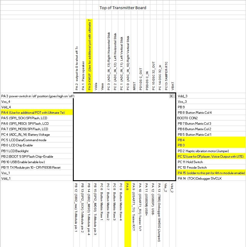
The X in the upper right corner is the designator for pin 1. The image is the same as looking down on the 7e board after removing the back.
computer nerd, hobby collector, proud father
Please Log in or Create an account to join the conversation.
- Fernandez
-
- Offline
- Posts: 983
You could also add in yellow (PC12 use for DFplayer, Voice Output with U7E)
It works I use it with latest test builds.
Please Log in or Create an account to join the conversation.
- compman2
-
- Offline
- Posts: 65
computer nerd, hobby collector, proud father
Please Log in or Create an account to join the conversation.
- compman2
-
- Offline
- Posts: 65
I have 2 boards ordered that /should/ work - same STM chip as the 7e (RBT6) and the other is the 256k version (RCT6)
robocog do you mind sharing a link to the boards that you purchased. I have been having trouble finding the RBT6 and RCT6 versions of the board, at least economically.
computer nerd, hobby collector, proud father
Please Log in or Create an account to join the conversation.
- mwm
-
- Offline
Oddly enough, doing this for switches & buttons - which is easier - may actually shrink the 7E code, since all the extra code for dealing with extra switches could be taken out. It would also take the existing button/switch table out of flash and move it to RAM, but we're short on that as well.
Do not ask me questions via PM. Ask in the forums, where I'll answer if I can.
My remotely piloted vehicle ("drone") is a yacht.
Please Log in or Create an account to join the conversation.
- robocog
-
- Offline
The boards and flash I have ordered and will hopefully drop through my letter box ...eventually
RCT6 (256k) - www.ebay.co.uk/itm/282308248979?_trksid=...e=STRK%3AMEBIDX%3AIT
RBT6 - (128k) - www.ebay.co.uk/itm/172437327465?_trksid=...e=STRK%3AMEBIDX%3AIT
Flash - SST25VF016B-75-4I-S2AF - www.ebay.co.uk/itm/281365536783?_trksid=...e=STRK%3AMEBIDX%3AIT
Regards
Rob
Please Log in or Create an account to join the conversation.
- Fernandez
-
- Offline
- Posts: 983
Please Log in or Create an account to join the conversation.
- 2hry
-
- Offline
- Posts: 18
Can I test the 1306-version too?
I already have a stm32f103rct6 board, 1306 Display and 25vf016.
Thanks
Please Log in or Create an account to join the conversation.
- mwm
-
- Offline
Do not ask me questions via PM. Ask in the forums, where I'll answer if I can.
My remotely piloted vehicle ("drone") is a yacht.
Please Log in or Create an account to join the conversation.
- robocog
-
- Offline
On the back it has an Atmel AT24 C08N 8K ( 1024 x 8 ) Two-wire Serial EEPROM
Bah!
Possibly no good then?
Regards
Rob
Please Log in or Create an account to join the conversation.
- mwm
-
- Offline
Do not ask me questions via PM. Ask in the forums, where I'll answer if I can.
My remotely piloted vehicle ("drone") is a yacht.
Please Log in or Create an account to join the conversation.
- robocog
-
- Offline
flash is a winbond 25Q16dvsig
All looks very neat
Have flashed the 256 7e bootloader, got the DFU prompt on USB insertion, and have installed the driver
Going to flash it, although there is nothing plugged in at all, just a bare board.
Journey has not been easy so far...but uphill I go
Regards
Rob
Please Log in or Create an account to join the conversation.
- robocog
-
- Offline
When I power the board with B8 and C9 shorted (button matrix for EXT) it goes into DFU mode !
However when shorting C7 B6 (ENT) it does not pick up as a USB drive - windows is showing unknown device
(could be the Winbond flash is incompatible?- or drivers?)
I could really do with a screen to be hooked up to it so I can "see" what is going on
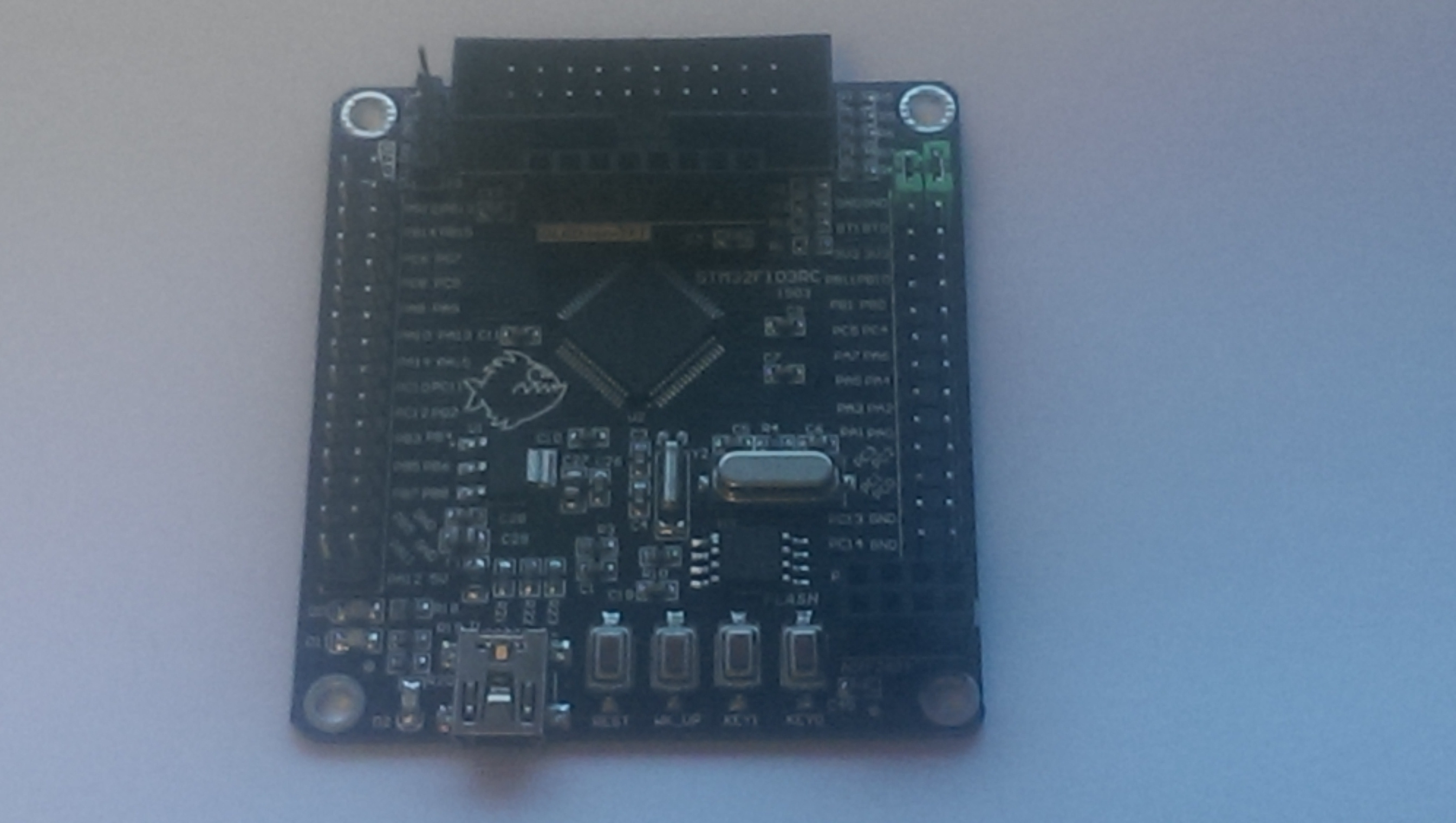
The board has an OLED or TFT plug
pins are labelled left to right
NC A0 RST CS SCL SDI GND 3V
Still trying to find if there is a schematic or any info out there for the board
STM32F103RC
STM_32Mini V2 1503
Beyond this
wiki.stm32duino.com/index.php?title=File...6-07-02_12.24.49.jpg
I have not found much out about it
Will keep searching
Regards
Rob
Please Log in or Create an account to join the conversation.
- Moeder
-
- Offline
- Posts: 796
edit: build for W25Q16 attached. No way for me to test this though...
Please Log in or Create an account to join the conversation.
- robocog
-
- Offline
Is this why shorting C7 and B6 together to emulate me holding ENT whilst powering on the board is not resulting in seeing a USB drive?
As I say shorting B8/C9 to emulate holding EXT whilst powering the board on does get me into DFU mode
(so it /seems/ as if its working OK as far as I can tell without a screen)
I have had a look at what is required to build it myself and I am still not understanding it (to say a steep learning curve is a major understatement)
Is there any way a simple inexpensive OLED can be coded in as well?
SSD1306 or similar?
I would be really grateful if this could be done
Regards
Rob
Please Log in or Create an account to join the conversation.
- Moeder
-
- Offline
- Posts: 796
Please Log in or Create an account to join the conversation.
- robocog
-
- Offline
same as before, just an unknown usb device
USB\VID_0000&PID_0000\5&23991BE5&0&5
My deviated std 7e works fine on the same lead into the same port, so hopefully it rules that out
Shows up as USB mass storage device
( USB\VID_0483&PID_5720\8D7933684856 )
Regards
Rob
Please Log in or Create an account to join the conversation.
- 2hry
-
- Offline
- Posts: 18
I have the same boards, but no display.
rbt6 board: removed i2c-flash, soldered sst25vf016 to the right pins.
rct6 board: removed spi-flash, soldered sst 25vf016 to the right Pins (onboard flash ce is not connected to boot1)
Bootloader flashed with flashloader Demonstrator.
I was not able to flash the dfu with the Walkera Dfu Tool, after driver change (wouldn´t recognize it).
But with deviation uploader I could flash the 2 boards with zip files. In Deviation uploader I can see the filesystem.
The rbt board works in USB mode, the rct board does not.
Maybe its the connection of boot0 and boot1 (different resistors)
Whats your plan for the power switch?
Please Log in or Create an account to join the conversation.
- robocog
-
- Offline
My RBT board does not have serial (unlike the RCT) - so using a CP2102 to get the bootloader on is no go - does yours have one?
I have an STlinkV2 clone on its way - hopefully tomorrow and I can try and flash the RBT board with bootloader and try again flashing
Have emailed the seller of the RCT board and they replied - and said they have some info on the board (hoping to clear up where key1 and key2 goes to etc...
Unfortunately the attachment got stripped by eBay and it was playing up trying to let me give them my email address to send it to
I did manage to send an image with my email address on- so fingers crossed they will send me something of use rather than just an image of the board I have in front of me
Will edit this after it has done flashing......fingers crossed...
Edited to add using the Java uploader (complete zip file) it says complete - and has assigned it a com port and it seems no matter what I do - including erasing and re-flashing the bootloader again via the CP2102 can't get it out of DFU mode - regardless of button matrix
- like your own experience - walkera DFU now refuses to work with it as it can't see it- tried all the drivers on zdiag :/
Noticed the internal flash start address is 0x08003000 under deviation uploader
Under the STM flash utility I used with the CP2102 it was 0x080000000
and under the deviation uploader @SPI Flash:Library - it is blank
Edited /again/ - removed the comport assigned (66) dfu driver from device mangler - and gained back the std STM DFU driver - and have connected back using DfuSe and reflashed the provided deviation zip file a few posts above
I am at least back to being able to select DFU mode by using the button matrix at power on - and get unknown USB device if EXT is not held in on boot
(ENT does nothing as far as PC seeing a USB drive)
This behavior is the same as my std 7e - DFU mode by holding EXT on powerup does not assign a com port
- sorry I missed your earlier question ref what am I going to do about the power switch...its something I have asked on here on how to implement
The closest to a diagram I have found is www.deviationtx.com/downloads-new/catego...power-switch-circuit
Till I have a working board with a file system and screen and stuff happening fairly predictably I am not worrying about it just yet
I have no doubt there will be a few getchas from not looking too deeply into this
Regards
Rob
Please Log in or Create an account to join the conversation.
-
Home

-
Forum

-
Development

-
Development

- Wishlist for a custom Transmitter board


