
- Posts: 18
Wishlist for a custom Transmitter board
- 2hry
-
- Offline
Less
More
10 Mar 2017 21:30 #60103
by 2hry
Replied by 2hry on topic Wishlist for a custom Transmitter board
PA9 and PA10 are RX and TX(USART1) to flash with serial adapter.
Did you rewire pin1 of the spi flash on the Rct board?
Did you rewire pin1 of the spi flash on the Rct board?
- robocog
-
- Offline
10 Mar 2017 23:08 - 11 Mar 2017 01:39 #60105
by robocog
Replied by robocog on topic Wishlist for a custom Transmitter board
LOL...so they are!
Not taken a soldering iron to either board till just now (just swapped flash on the RBT board)
What do I need to do on the pin1 of the spi flash on the RCT board?
I have just flashed the std 7e bootloader on the RBT board using the cp2102 serial!
I flashed the latest nightly for std 7e using DfuSe
I have swapped the SPI flash on the RBT board for a sst25vf016b
It's just a straight swap of components making sure the dot is aligned with the board marking's dot yes?
Pressing Ext gets me into DFU mode
holding ent however does not get me a a removable usb device - just an unknown device with blank vid/pid
Re-flashing deviation does not change this behavior
This is the same for both boards :/
Is there any way of checking the flash memory via the flash tool? (or maybe another tool)
I can get into DFU mode from USB and I can use serial
Do I need to re flash the bootloader after swapping the flash memory on the RBT board?
Regards
Rob
Last edit: 11 Mar 2017 01:39 by robocog.
- mwm
-
- Offline
11 Mar 2017 02:13 #60107
by mwm
The bootloader loads at the start of flash - 0x080000000 - and the Tx firmware loads above that, rounded to 0x3000 on these chips. So this is what you'd expect.
Do not ask me questions via PM. Ask in the forums, where I'll answer if I can.
My remotely piloted vehicle ("drone") is a yacht.
Replied by mwm on topic Wishlist for a custom Transmitter board
robocog wrote: Noticed the internal flash start address is 0x08003000 under deviation uploader
Under the STM flash utility I used with the CP2102 it was 0x080000000
The bootloader loads at the start of flash - 0x080000000 - and the Tx firmware loads above that, rounded to 0x3000 on these chips. So this is what you'd expect.
Do not ask me questions via PM. Ask in the forums, where I'll answer if I can.
My remotely piloted vehicle ("drone") is a yacht.
- 2hry
-
- Offline
Less
More
- Posts: 18
11 Mar 2017 12:18 #60124
by 2hry
Replied by 2hry on topic Wishlist for a custom Transmitter board
direct replacement is not right, connected to the wrong pins according to devo7e hardware diagram.
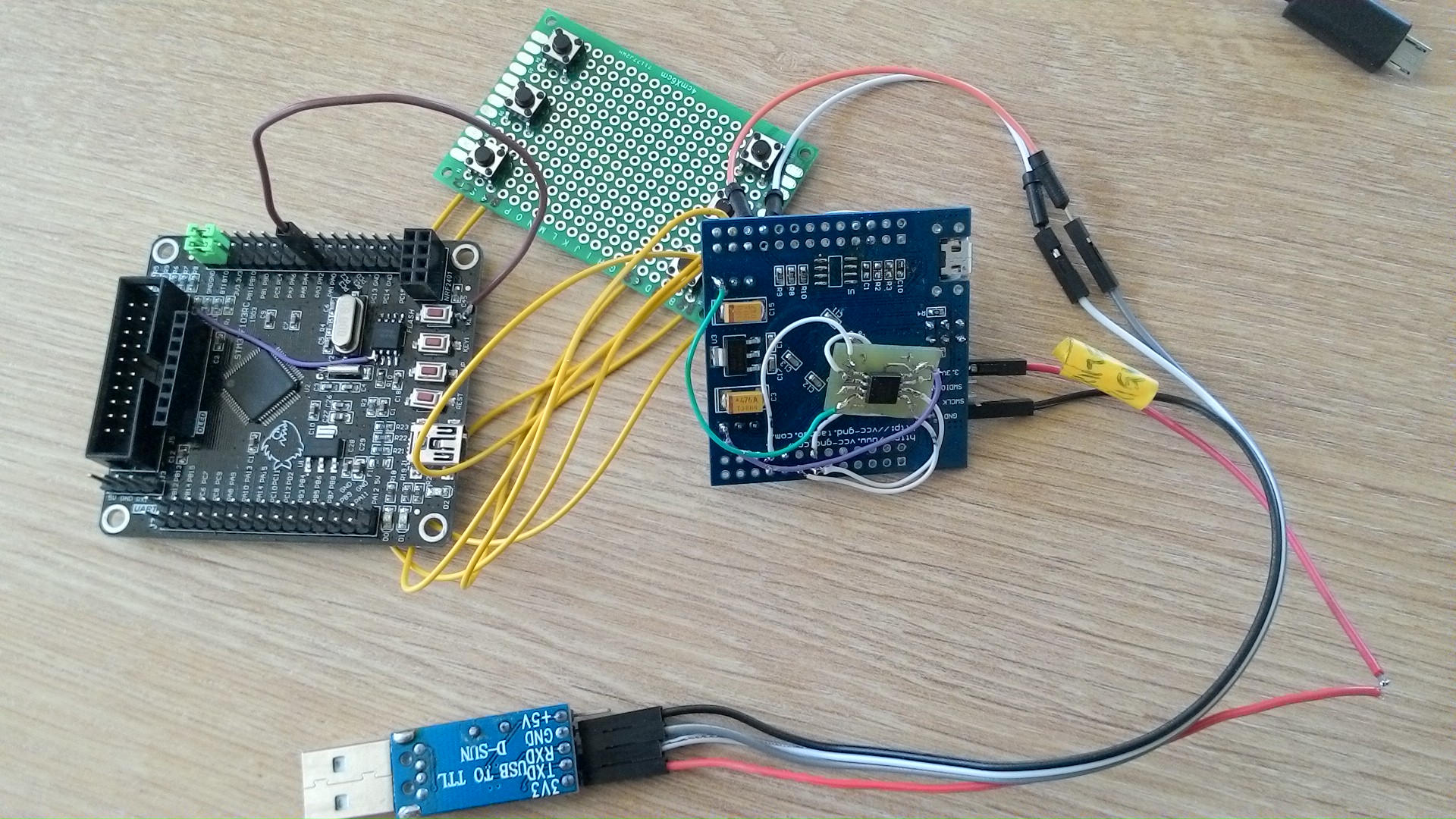
I made an adapter to test.
Pin 1 of the spi flash on the rct board is connected wrong. I lifted the leg, and didnt solder it on. With help of a jumper wire - Connection to the resistors of Boot1. The connection of Boot1 and Boot0 is different on this board. When i have some spare time, I´m going to desolder all the resistors from the jtag header, unneeded buttons and leds, and try again.
- robocog
-
- Offline
11 Mar 2017 15:09 - 11 Mar 2017 15:35 #60129
by robocog
Replied by robocog on topic Wishlist for a custom Transmitter board
So on the RBT board - the original (and wrong) flash pins are not correct ?
Possibly explains why I cant get it to go into USB or flash the library from Dfuse
So in that ^^ image - wiring the flash as shown - it does all work? - flashing to library from Dfuse and as a removable device?
I can follow / understand / make out
SPI Flash - RBT board
VDD -3.3v
VSS - GND
CE - B2
SO - A6
SCK - A5
SI - A7
BUT what about WP and Hold?
Not needed?
Regards
Rob
Last edit: 11 Mar 2017 15:35 by robocog.
- robocog
-
- Offline
11 Mar 2017 19:14 #60132
by robocog
Replied by robocog on topic Wishlist for a custom Transmitter board
Just wired the flash to a separate board - as you have...reflashed bootloader (std 7e)
Wired as per my last post
(left WP and Hold floating on the spi flash)
Reflashed deviation 7e std nightly...still no usb with ent held in on powerup
Regards
Rob
Wired as per my last post
(left WP and Hold floating on the spi flash)
Reflashed deviation 7e std nightly...still no usb with ent held in on powerup
Regards
Rob
- 2hry
-
- Offline
Less
More
- Posts: 18
11 Mar 2017 19:33 #60133
by 2hry
Replied by 2hry on topic Wishlist for a custom Transmitter board
Wp and Hold are connected to 3.3v.
Rbt board: flashed devo7e with deviation uploader. removable drive is working when holding Ent button. When I hold no button and plugin USB it it always shown in Dfu Mode in the Device Manager in Windows. Original Devo would not be in Dfu Mode, I assume.
Rct Board: flashed devo7e256 with deviation uploader. removable drive not working, but I can see the filesystem in deviation uploader. It is always in Dfu Mode when I plug it in. Need further testing.
- robocog
-
- Offline
11 Mar 2017 21:47 #60134
by robocog
Replied by robocog on topic Wishlist for a custom Transmitter board
WP and hold now connected to 3.3v
Reflashed (latest nightly zip) using deviation uploader (the java one)
says it has completed - I can even see and edit files from the apps file manager, thinking this time it was sorted...
Press ent and power up again
Unknown USB device
The only thing that "looks" odd during flashing
@Internal Flash 0x08003000 116kb 116 sectors 1kb size
@SPI Flash:Config 0x00000000 128kb 32 sectors 4kb size
@SPI Flash:Library - all fields are blank
Go back into DFU mode, flash using dfuse using latest nightly
No difference, still no USB removable device
I know I'm getting closer as I am able to read and edit via the file manager in the deviation uploader (unless I'm editing the local file NOT the files on the TX!)
Regards
Rob
- 2hry
-
- Offline
Less
More
- Posts: 18
11 Mar 2017 22:20 - 11 Mar 2017 22:21 #60135
by 2hry
Replied by 2hry on topic Wishlist for a custom Transmitter board
I tested the Rbt board again.
Usb drive works only when A3 is connected to GND. (Something with the Power Switch circuit)
Usb drive works only when A3 is connected to GND. (Something with the Power Switch circuit)
Last edit: 11 Mar 2017 22:21 by 2hry.
- robocog
-
- Offline
11 Mar 2017 23:47 #60136
by robocog
Replied by robocog on topic Wishlist for a custom Transmitter board
Indeed so it does 
Cant thank you enough for this
USB shows up as long as A3 is grounded
Looking at the switch circuit diagram from the devo8 - there is a 1k resistor and a 1n4148 and a 1m resistor going to ground from A3
I think I have some of the parts from that diagram so I will try and at least do that part of it
I'm guessing the diode is only there to stop the switches V feed at the center of the power slide switch going into the A3 pin...and the 1M and 100k resistors are there for another reason...which is not clear to me ...yet
I am logging the steps I am doing to make repeating them without the frustration nice and easy to follow from a newbies perspective
Thanks once again for your support so far
I would truly have been lost without it
Please do keep sharing your findings with these boards
I feel a massive milestone has been achieved by getting this far and looking forward to getting this to actually control something
Regards
Rob
- robocog
-
- Offline
12 Mar 2017 00:29 #60138
by robocog
Replied by robocog on topic Wishlist for a custom Transmitter board
- robocog
-
- Offline
12 Mar 2017 18:10 #60150
by robocog
Just had a play with the RCT board
With A3 to ground it found the drivers straight away and shows as removable drive - and PC kindly asks if I would I like to format it (it shows up as 2MB)
I of course answer yes....but it fails
Tracing where the flash pins go it looks like they are all as per the RCT setup we have working (+v A5 A7 A6 GND)
...but the CE enable pin on the flash goes to PA2 rather than PB2 according to my continuity meter
Hold and WP seem to also be tied to +V according to my continuity meter
I can only see 2 ways around this, lift leg and wire to B2 - maybe direct to cpu as there is other circuitry (resistor R2 480ohm and maybe something else?)
Change code to reflect a different enable pin (moon on a stick request?)
Regards
Rob
Replied by robocog on topic Wishlist for a custom Transmitter board
2hry wrote: Wp and Hold are connected to 3.3v.
Rbt board: flashed devo7e with deviation uploader. removable drive is working when holding Ent button. When I hold no button and plugin USB it it always shown in Dfu Mode in the Device Manager in Windows. Original Devo would not be in Dfu Mode, I assume.
Rct Board: flashed devo7e256 with deviation uploader. removable drive not working, but I can see the filesystem in deviation uploader. It is always in Dfu Mode when I plug it in. Need further testing.
Just had a play with the RCT board
With A3 to ground it found the drivers straight away and shows as removable drive - and PC kindly asks if I would I like to format it (it shows up as 2MB)
I of course answer yes....but it fails
Tracing where the flash pins go it looks like they are all as per the RCT setup we have working (+v A5 A7 A6 GND)
...but the CE enable pin on the flash goes to PA2 rather than PB2 according to my continuity meter
Hold and WP seem to also be tied to +V according to my continuity meter
I can only see 2 ways around this, lift leg and wire to B2 - maybe direct to cpu as there is other circuitry (resistor R2 480ohm and maybe something else?)
Change code to reflect a different enable pin (moon on a stick request?)
Regards
Rob
- Moeder
-
- Offline
Less
More
- Posts: 796
12 Mar 2017 18:23 #60151
by Moeder
Replied by Moeder on topic Wishlist for a custom Transmitter board
It is not completely unreasonable, as there others before thinking about putting a lot more pin configuration options in hardware than only the RF-module pins and PA options. But it would be not something done very quickly.
robocog wrote: Change code to reflect a different enable pin (moon on a stick request?)
- robocog
-
- Offline
12 Mar 2017 19:00 - 12 Mar 2017 19:46 #60153
by robocog
Replied by robocog on topic Wishlist for a custom Transmitter board
The more stuff to tinker with in the ini the merrier -certainly for non in depth technical types such as myself ")
The ini usually lives on the removable usb drive though...and I cant get to the usb drive so I guess /this/ example would need hard coding?
In fact - can't CE just be held low permanently?
(wire CE to gnd?)
Edited to add
A glance at the spec sheet for the flash chip
"The /CS input must track the VCC supply level at power up and power down
(see “Write Protection” and figure 39). If needed a pull up resister on /CS can be used to accomplish this"
So tying it permanently to ground is not going to be a solution
Currently the CS pin is being held high when the board is powered
IF the flash pin is really connected to PA2 then that is a problem
If A2 gets output to 0 it shuts off the TX according to the hardware connections on the wiki
I guess this would also make a simple code change (LOL) a lot more serious/unworkable
As a test I just put a2 to ground after the board had booted and shown me the drive
I tried to format the drive...but it timed out rather than just instantly denying my request
I should really put a piezo on it to see if this does indeed power the board down
(or a screen so I can see!)
.but that would not work either I guess as my 7e does not beep in DFU or USB modes
Regards
Rob
Last edit: 12 Mar 2017 19:46 by robocog.
- 2hry
-
- Offline
Less
More
- Posts: 18
12 Mar 2017 20:30 - 12 Mar 2017 20:41 #60160
by 2hry
Replied by 2hry on topic Wishlist for a custom Transmitter board
I tinkered with the rct board again, and couldn´t get it to work.
Ce of the spi Flash(sst vf016) is wired to R2, like in my picture above.
3 of the 4 switches, 2 additional leds, and resistors, RTC Crystal+2caps, Resistors from Boot0 and Boot1 got desoldered and tested inbetween.
Resistors from Boot0 and Boot1 changed to 100K, as it is on my Rbt board.
no success!
When I read that it works for you with Dfuse, I removed all DFUdrivers one after another, and Dfuse was able to recognize it as Devo7e.
And now it worked. Dfu upgrade and then the USB drive showed up. Copied the filesystem over -- 2 Boards working so far.
I´m trying to build the power switch circuit from scrap parts this week
Last edit: 12 Mar 2017 20:41 by 2hry.
- robocog
-
- Offline
12 Mar 2017 20:38 #60161
by robocog
Congrats on sussing it
So just lift leg and wire to mcu side of R2 would be enough to satisfy the flash?
Regards
Rob
Replied by robocog on topic Wishlist for a custom Transmitter board
2hry wrote: I tinkered with the rct board again, and couldn´t get it to work.
Ce of the spi Flash(sst vf016) is wired to R2, like in my picture above.
3 of the 4 switches, 2 additional leds, and resistors, RTC Crystal+2caps, Resistors from Boot0 and Boot1 got desoldered and tested inbetween.
Resistors from Boot0 and Boot1 changed to 100K, as it is on my Rbt board.
no success!
When I read that it works for you with Dfuse, I removed all drivers one after another, and Dfuse was able to recognize it as Devo7e.
And now it worked. Dfu upgrade and then the USB drive showed up. Copied the filesystem over -- 2 Boards working so far.
I´m trying to build the power switch circuit from scrap parts this week
Congrats on sussing it
So just lift leg and wire to mcu side of R2 would be enough to satisfy the flash?
Regards
Rob
- robocog
-
- Offline
12 Mar 2017 20:56 - 12 Mar 2017 21:05 #60162
by robocog
Just went for it
managed to lift the trace from under CE in lifting the leg :/
...and I have just copied the FS over!
Piezo seeked out and soldered up wired straight to gnd and A1
Powering on gives the start tone
It lives!
Regards
Rob
Replied by robocog on topic Wishlist for a custom Transmitter board
Just went for it
managed to lift the trace from under CE in lifting the leg :/
...and I have just copied the FS over!
Piezo seeked out and soldered up wired straight to gnd and A1
Powering on gives the start tone
It lives!
Regards
Rob
Last edit: 12 Mar 2017 21:05 by robocog.
- Moeder
-
- Offline
Less
More
- Posts: 796
13 Mar 2017 13:14 #60168
by Moeder
Replied by Moeder on topic Wishlist for a custom Transmitter board
Was that using the special flash chip build I made for you?
- robocog
-
- Offline
13 Mar 2017 13:28 #60169
by robocog
Replied by robocog on topic Wishlist for a custom Transmitter board
Yes...so thank you very much for providing it
I can add remove and edit the files so all of that side of things seems to be working just great!
Regards
Rob
I can add remove and edit the files so all of that side of things seems to be working just great!
Regards
Rob
- Moeder
-
- Offline
Less
More
- Posts: 796
22 Mar 2017 15:10 #60533
by Moeder
Replied by Moeder on topic Wishlist for a custom Transmitter board
Any progress on this?
Time to create page: 0.208 seconds
-
Home

-
Forum
-
Development
-
Development
- Wishlist for a custom Transmitter board