- Posts: 799
Jumper T8SG - First TX stock running on Deviation
- dc59
-
- Offline
Fernandez wrote: Can you confirm it is possible to use single liion cell and charge over USB? (I have mod my 7e and like it so much, it is perfect, charge it anyware from USB is great.)
Jumper did NOT design charge circuit on PCB , it can't be charged battery via USB port.
Please Log in or Create an account to join the conversation.
- dc59
-
- Offline
- Posts: 799
Bug wrote: Sorry to bother you again vlad, but I've just calculated the screw distance of the gimbals on your photo, and it seems to be the same 35mm as the original gimbals had ?
Can you confirm this or have I estimated the wrong distance of the connector pins?
Which distance do you need ? I'm not really understand , could you show me it on picture?
Please Log in or Create an account to join the conversation.
- yets
-
- Offline
- Posts: 127
dc59 wrote:
yets wrote: Is it safe to assume that Jumper have stopped working on Hall gimbals for Devo series?
Jumper got some problems when they tested hall gimbals on DEVO TX, it will take some more time to solve this.
Thanks for the update. It has been quite a few months since they started work on it. I'm sure many would be disappointed if they gave up on it
Please Log in or Create an account to join the conversation.
- vlad_vy
-
- Offline
- Posts: 3333
I have interchanged switch position for "H" and "B", interchange connectors for "G" and "H" switches, interchange connectors for "A" and "B" switches. Now I have next switch positions:
__H___________A__
D___G______C___B
SWH = HOLD/RUD DR
SWG = GEAR
SWA = FMODE
SWB = AIL DR
SWC = MIX
SWD = ELE DR
Also, changed switch mapping at "capabilities.h":
#ifdef UNDEF_INP
#define INP_RUD_DR0 INP_SWH0
#define INP_RUD_DR1 INP_SWH1
#define INP_ELE_DR0 INP_SWD0
#define INP_ELE_DR1 INP_SWD1
#define INP_AIL_DR0 INP_SWB0
#define INP_AIL_DR1 INP_SWB1
#define INP_FMOD2  INP_SWA2
#define INP_MIX0   INP_SWC0
#define INP_MIX1   INP_SWC1
#define INP_MIX2   INP_SWC2
#define INP_GEAR0  INP_SWG0
#define INP_GEAR1  INP_SWG1
#endif

#ifdef CHANMAP
//These are legacy mappings
  CHANMAP("DR",     SWB1)
  CHANMAP("RUD DR", SWH1)
  CHANMAP("ELE_DR", SWD1)
  CHANMAP("AIL_DR", SWB1)
  CHANMAP("GEAR",   SWG1)
//Current mappings
  CHANMAP("DR0", SWB0)
  CHANMAP("DR1", SWB1)
  CHANMAP("RUD DR0", SWH0)
  CHANMAP("RUD DR1", SWH1)
  CHANMAP("ELE DR0", SWD0)
  CHANMAP("ELE DR1", SWD1)
  CHANMAP("AIL DR0", SWB0)
  CHANMAP("AIL DR1", SWB1)
  CHANMAP("HOLD0", SWH0)
  CHANMAP("HOLD1", SWH1)
  CHANMAP("FMODE0", SWA0)
  CHANMAP("FMODE1", SWA1)
  CHANMAP("FMODE2", SWA2)
  CHANMAP("MIX0", SWC0)
  CHANMAP("MIX1", SWC1)
  CHANMAP("MIX2", SWC2)
  CHANMAP("GEAR0", SWG0)
  CHANMAP("GEAR1", SWG1)
#endif
Now I can import all models from devo8 without any changes. With one exception, I need manually correct 2-pos to 3-pos switch mapping: for example change "SW D1" (ELE DR1) to "!SW D0".
Please Log in or Create an account to join the conversation.
- vlad_vy
-
- Offline
- Posts: 3333
I don't understand why "T8SG V2 Plus" RF power output is twice higher than with other 4in1 modules (I have four modules).
Devo 8s (4in1 module) - Jumper T8SG V2 Plus (4in1 module)
Protocol Devo (CYRF6936)
150mW = 74.38mW = 142.95mW
100mW = 63.10mW = 121.96mW
30mW = 33.77mW = 65.21mW
10mW = 8.48mW = 19.57mW
3mW = 3.27mW = 8.48mW
1mW = 880uW = 2.95mW
300uW = 180uW = 750uW
100uW = 50uW = 240uW
Protocol Hubsan4 (A7105)
150mW = 79.43mW = 142.95mW
100mW = 79.43mW = 142.95mW
30mW = 76.86mW = 132.04mW
10mW = 53.53mW = 45.41mW
3mW = 20.21mW = 18.36mW
1mW = 6.52mW = 5.18mW
300uW = 3.61mW = 2.75mW
100uW = 1.63mW = 1.28mW
Protocol S-FHSS (CC2500)
150mW = 57.17mW = 108.26mW
100mW = 51.79mW = 93.63mW
30mW = 14.22mW = 38.52mW
10mW = 4.25mW = 12.92mW
3mW = 1.28mW = 4.54mW
1mW = 0.38mW = 1.42mW
300uW = 0.16mW = 0.33mW
100uW = 0.05mW = 0.11mw
Protocol SymaX (NRF24L01)
150mW = 79.43mW = 148.74mW
100mW = 79.43mW = 148.74mW
30mW = 76.86mW = 148.74mW
10mW = 63.10mW = 121.96mW
3mW = 63.10mW = 121.96mW
1mW = 20.21mW = 38.52mW
300uW = 20.21mW = 38.52mW
100uW = 20.21mW = 38.52mW
Please Log in or Create an account to join the conversation.
- Bug
-
- Offline
- Posts: 19
Just the distance of the screws of the gimbal, if there is a chance to fit them into the v1 version of the transmitter. Frsky gimbals are great and rather cheap to get, but way too big be fitted into a jumper.Which distance do you need ? I'm not really understand , could you show me it on picture?
Please Log in or Create an account to join the conversation.
- vlad_vy
-
- Offline
- Posts: 3333
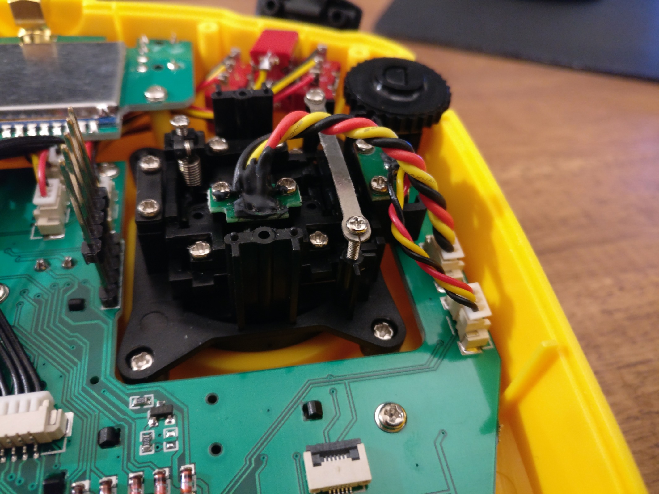
With "Jumper T8SG V2 Plus" there is RF noise to Hall sensor wires problem. It depends from used protocol and output power. The simple solution is to unplug wires, twist the wires to protect them from electromagnetic interference and plug them back in.
Please Log in or Create an account to join the conversation.
- Fernandez
-
- Offline
- Posts: 983
Higher voltage, at the PA/LNA chip, better matching between antenna and module, or on the module itself. (the first modules had a long open trace) Only think i do not like so much there is no ceramic BPF filter at the output of the module.....
With regards to RFI, I do not like at all, open pins to the CPU without any filtering. We could surely add 100pf capacitor on all input lines, switches and adc pots input at the pcp, to gnd. Best design would have those capcitors close to the CPU. When using lower frequency UHF modules at 1watt , the pick up will even be worse....(I doubt the radio could have CE with this problem...)
Other easy solution, to make a bit more robust against RFI, we could possible add some ferrite rings or ferrite clamps around the hall cables and switches.
www.ebay.ie/itm/5X-3-5mm-Noise-Suppresso...ack-MW-/192382534342
Please Log in or Create an account to join the conversation.
- vlad_vy
-
- Offline
- Posts: 3333
Please Log in or Create an account to join the conversation.
- vlad_vy
-
- Offline
- Posts: 3333
Bug wrote: Sorry to bother you again vlad, but I've just calculated the screw distance of the gimbals on your photo, and it seems to be the same 35mm as the original gimbals had ?
Can you confirm this or have I estimated the wrong distance of the connector pins?
35x42mm
Please Log in or Create an account to join the conversation.
- Philipp
-
- Offline
- Posts: 18
Twisting the wires did not fix the problem for me, there was still some jitter on the gimbal channels (Ch 1 - 4, +/- 12 around center). In my case the batteries were partially depleted and not in the best shape.vlad_vy wrote: If Jumper use Devo 7e diagram for T8SG, it has RC filters (100Ohm + 100pF) at ADC inputs. At least, twisting wires completely fix the problem for user that note this problem.
After switching them out for fully charged, high quality ones the jitter was gone. Interestingly i could only notice jitter when using the CC2500 module / the FrSky protocol. The hall sensors seem to be very sensitive to fluctuations in the battery voltage.
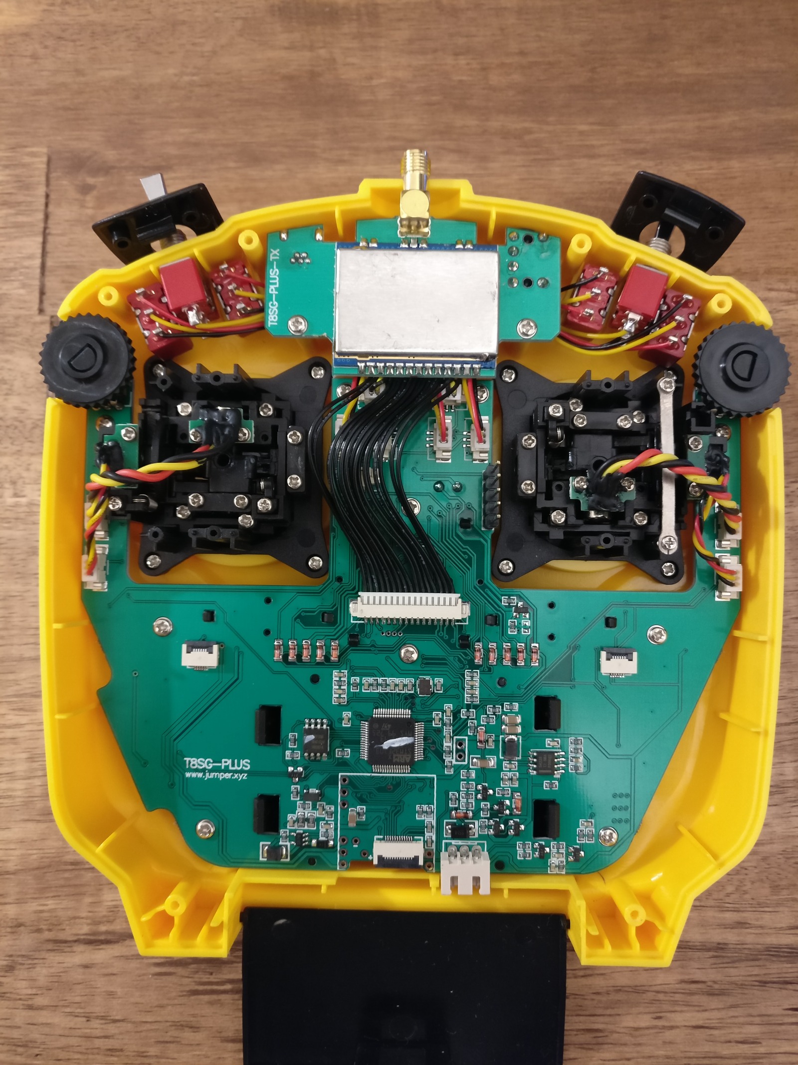
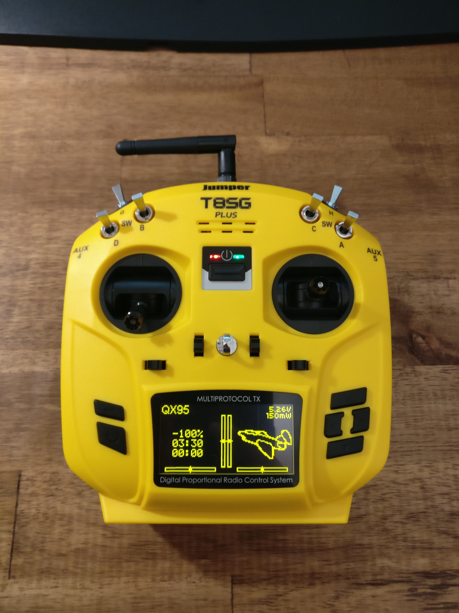
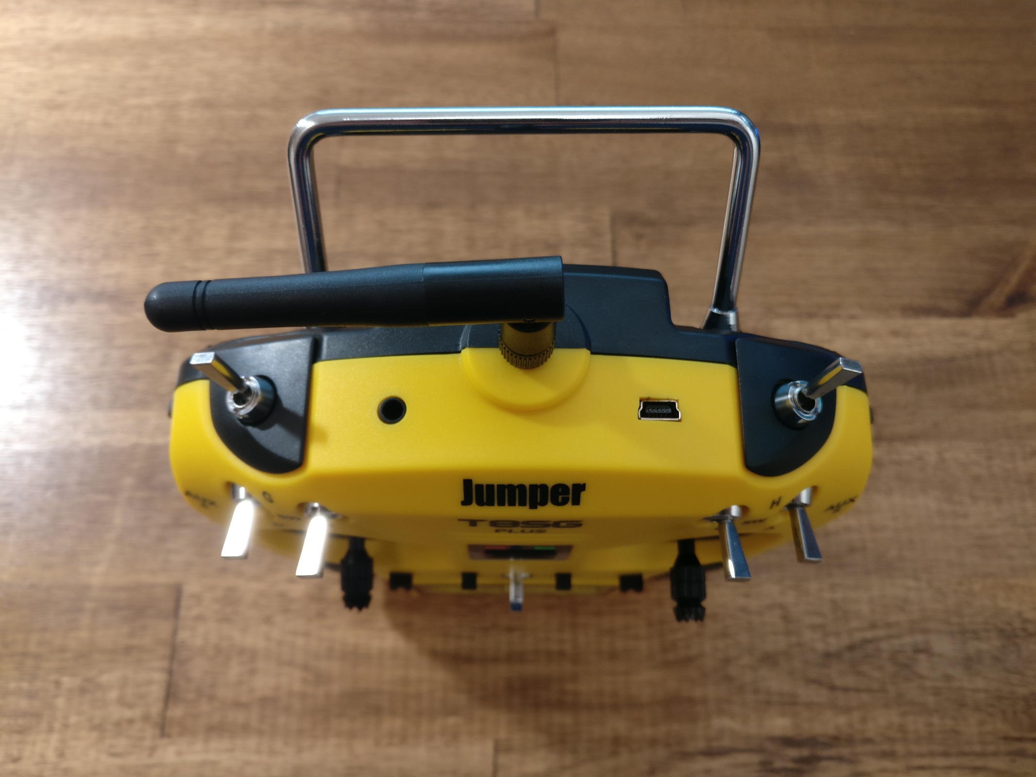
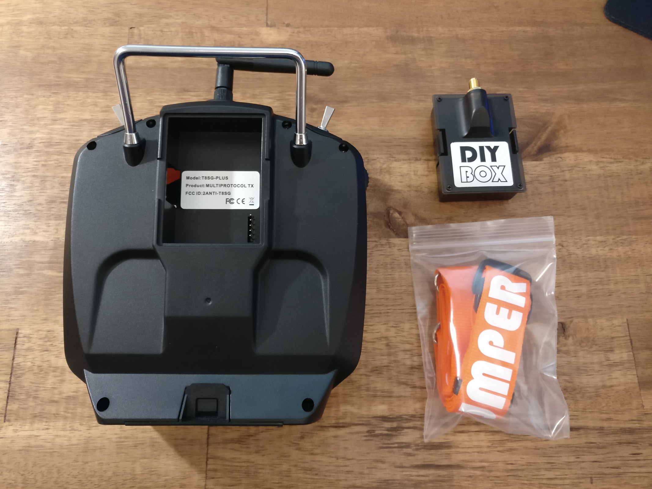
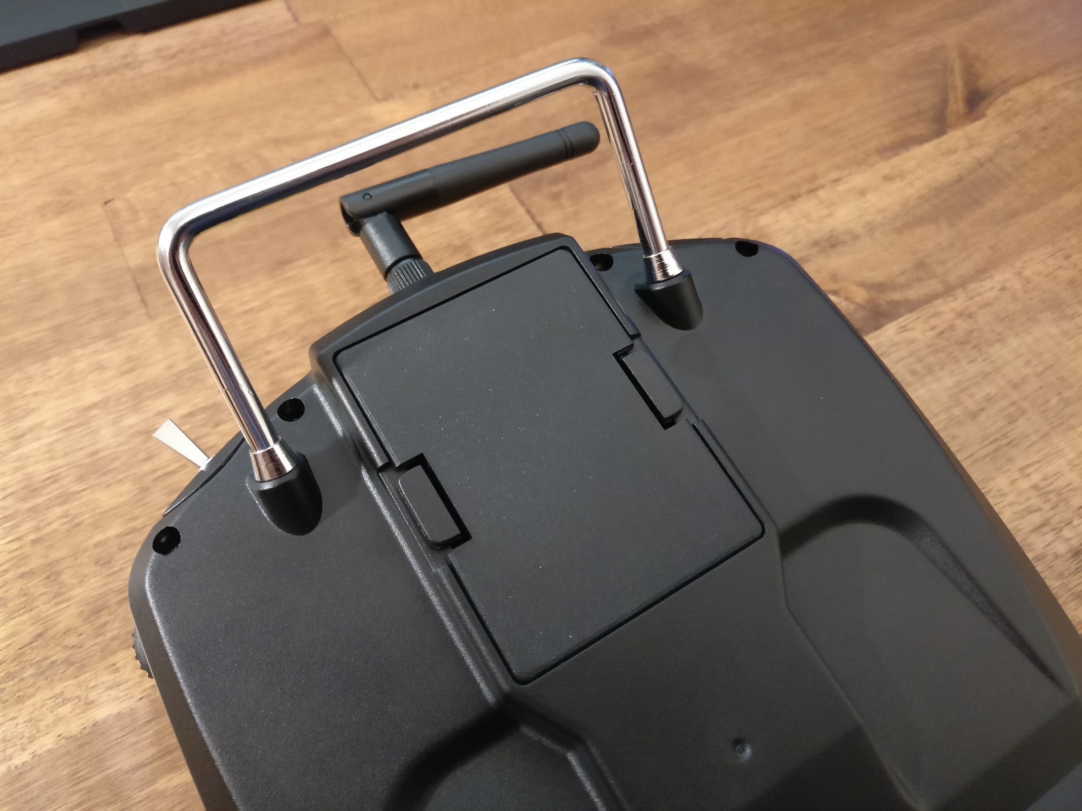
I've attached some pictures of the exterior and interior of the T8SG V2 Plus.
I really like the included JR module case. Please note that I've added the RP-SMA pigtail, it is not included with the case.
Since the multimodule already supports all protocols I need, I've exchanged the empty module for the black blanking plate which was included with my original Taranis X9E ( alofthobbies.com/frsky-taranis-module-cover.html or maybe www.banggood.com/Transmitter-Module-Case...rch&cur_warehouse=CN ):
I've also made a quick five minute video with my initial thoughts about the T8SG V2 Plus:
Please Log in or Create an account to join the conversation.
- vlad_vy
-
- Offline
- Posts: 3333
Please Log in or Create an account to join the conversation.
- Phobos
-
- Offline
- Posts: 16
Please Log in or Create an account to join the conversation.
- vlad_vy
-
- Offline
- Posts: 3333
With 4xAA battery you are very close to the edge of LDO capabilities (dropout voltage): 4.8V - 3.3V = 0.5V
Please Log in or Create an account to join the conversation.
- Philipp
-
- Offline
- Posts: 18
vlad_vy wrote: They all connected to 3.3V and ground.
With 4xAA battery you are very close to the edge of LDO capabilities (dropout voltage): 4.8V - 3.3V = 0.5V
A 2s LiFe with 6.6V nominal and a relatively flat discharge curve might be a better option, or do you think that heat dissipation in the LDO would be too high?
According to the BG description, a 2S LiPo may be used, so it should be fine?
Please Log in or Create an account to join the conversation.
- vlad_vy
-
- Offline
- Posts: 3333
Please Log in or Create an account to join the conversation.
- dc59
-
- Offline
- Posts: 799
Please Log in or Create an account to join the conversation.
- Fernandez
-
- Offline
- Posts: 983
I did a lot of testing, but can't put my finger on the cause. At least it is not caused by the Tx internal regulator, as replaced an tested with adding large capacitors at 3v3rail, neither by noise at the ADC pin for Txbat sense (also adding capacitors).
Just wondering if same issue is also in jumper..
Please Log in or Create an account to join the conversation.
- dc59
-
- Offline
- Posts: 799
Please Log in or Create an account to join the conversation.
- Iroquois
-
- Offline
There is no such thing as a 'hall effect gimbal'. A gimbal is a gimbal and can operate a conventional potentiometer or a hall effect sensor. If your conventional pot has problems centering, you simply need to excercise it a few times.
Please Log in or Create an account to join the conversation.
-
Home

-
Forum

-
General

-
General Discussions

- Jumper T8SG - First TX stock running on Deviation

