
- Posts: 58
Single-Board Universal Module
- octagon
-
- Offline
Less
More
04 Apr 2015 03:48 - 04 Apr 2015 04:11 #30775
by octagon
Replied by octagon on topic Single-Board Universal Module
The lower cost Murata filter is pretty much identical. I'll see if I can run a sim on the discrete filter.
Nice work on that PCB!
I also made a version. My home demo Eagle does not allow me to change mid-layers, so they are intact, but they look OK.
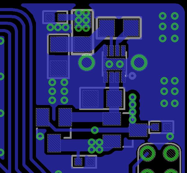
I added a filter to the DC 3.3V switcher, which may knock down HF noise some ~60dB, according to LTspice. I added an 0603 inductor (to save space) and another 0402 1uF. Inductor is low cost, but I hate to add parts to the BOM. An 0805 may fit but its quite close to the edge. I put the "gate bleeders" on layer 1.
My lib has the original footprint for the switcher, it looks like yours been improved(?).
The layouts are not otherwise very different. Use as you see fit.
Nice work on that PCB!
I also made a version. My home demo Eagle does not allow me to change mid-layers, so they are intact, but they look OK.
I added a filter to the DC 3.3V switcher, which may knock down HF noise some ~60dB, according to LTspice. I added an 0603 inductor (to save space) and another 0402 1uF. Inductor is low cost, but I hate to add parts to the BOM. An 0805 may fit but its quite close to the edge. I put the "gate bleeders" on layer 1.
My lib has the original footprint for the switcher, it looks like yours been improved(?).
The layouts are not otherwise very different. Use as you see fit.
Last edit: 04 Apr 2015 04:11 by octagon.
- PhracturedBlue
-
Topic Author
- Offline
Less
More
- Posts: 4403
04 Apr 2015 04:12 #30776
by PhracturedBlue
Replied by PhracturedBlue on topic Single-Board Universal Module
do you have an inductor in mind? Most of the 0603 2.2uH inductors I looked at either had very low current ratings, or a very low saturation current which I think would reduce the effectiveness of the filter. I can probably fit a 0805 inductor if I move things around.
- octagon
-
- Offline
Less
More
- Posts: 58
04 Apr 2015 04:33 #30777
by octagon
Replied by octagon on topic Single-Board Universal Module
octagon wrote: The lower cost Murata filter is pretty much identical. I'll see if I can run a sim on the discrete filter.
RFsim99 did not give happy results for the discrete circuit. The integrated filter is a safer bet.
Nice work on that PCB!
I also made a version. My home demo Eagle does not allow me to change mid-layers, so they are intact, but they look OK.
I added a filter to the DC 3.3V switcher, which may knock down HF noise some ~60dB, according to LTspice. I added an 0603 inductor (to save space) and another 0402 1uF. Inductor is low cost, but I hate to add parts to the BOM. An 0805 may fit but its quite close to the edge. I put the "gate bleeders" on layer 1.
My lib has the original footprint for the switcher, it looks like yours been improved(?).
The layouts are not otherwise very different. Use as you see fit.
- octagon
-
- Offline
Less
More
- Posts: 58
04 Apr 2015 04:36 - 04 Apr 2015 04:38 #30778
by octagon
Replied by octagon on topic Single-Board Universal Module
part-number of my 0603 inductor is on the schematic, along with critical data. Saturation current is a bit low, but this coil is not swinging a big load like the other one, so I do not think it will saturate.
445-3606-1-ND
445-3606-1-ND
Last edit: 04 Apr 2015 04:38 by octagon.
- PhracturedBlue
-
- Offline
Less
More
- Posts: 4403
04 Apr 2015 05:16 #30779
by PhracturedBlue
Replied by PhracturedBlue on topic Single-Board Universal Module
How about this (updates are checked in if you want to look at it in eagle):
I used the same 0805 2.2uH inductor I use in the previous stage. I mounted them perpendicular. I'm not sure if coupling will be an issue since they should have constant current.
I used the same 0805 2.2uH inductor I use in the previous stage. I mounted them perpendicular. I'm not sure if coupling will be an issue since they should have constant current.
- PhracturedBlue
-
- Offline
Less
More
- Posts: 4403
04 Apr 2015 15:07 #30785
by PhracturedBlue
Replied by PhracturedBlue on topic Single-Board Universal Module
Here is the board with the band-pass filter:
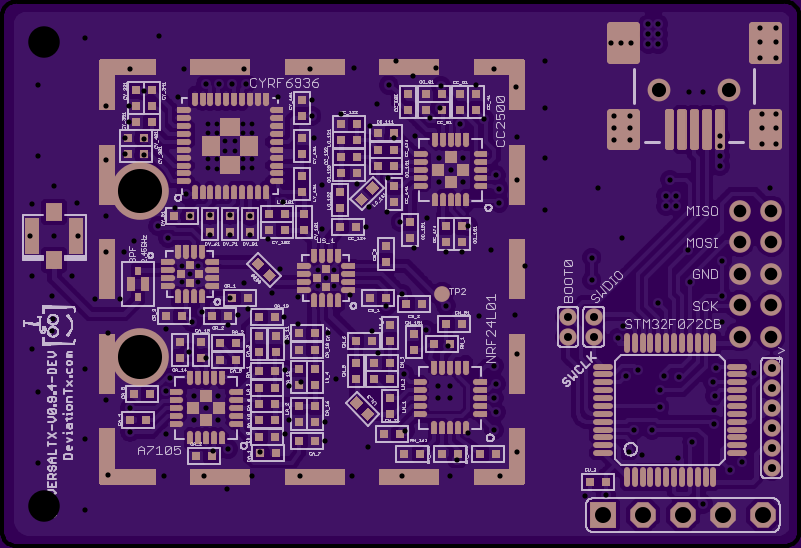
Everything is checked in
Everything is checked in
- Fernandez
-
- Offline
Less
More
- Posts: 983
04 Apr 2015 17:31 #30793
by Fernandez
Replied by Fernandez on topic Single-Board Universal Module
Nice !! Wel done!
One more comment I would rotate the antenna out ipx connector and route it straight to bpf, with shortest path to the bandpass, so remove the unwanted "stripline".
Extra Via´s could be added in the ground plane areas and RF spots, the more the better.
One more comment I would rotate the antenna out ipx connector and route it straight to bpf, with shortest path to the bandpass, so remove the unwanted "stripline".
Extra Via´s could be added in the ground plane areas and RF spots, the more the better.
- PhracturedBlue
-
- Offline
Less
More
- Posts: 4403
04 Apr 2015 18:25 #30796
by PhracturedBlue
Replied by PhracturedBlue on topic Single-Board Universal Module
Should I be concerned with fragmenting the 3.3V plane too much? when I go crazy with ground vias, it tends to break up the 3.3V plane. I've tried to keep a good via density while still ensuring a robust power plane. But maybe I'm focusing on the wrong things.
I fixed the BPF:
I fixed the BPF:
- Fernandez
-
- Offline
Less
More
- Posts: 983
04 Apr 2015 19:41 #30798
by Fernandez
Replied by Fernandez on topic Single-Board Universal Module
Yup it is better as such. The best designs have the shortest and minimum of traces.
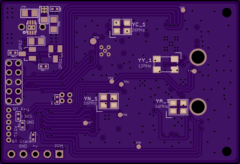
I think there are still some cosmetic optimalisations possible on the digital lanes, the HF looks neat. Such as near TP8, whuy not go straight under the resonator?
And for instance trace under YA_1, also 90degree angles, I would avoid just for the looks.
But great job!! My full credits for all your time spend!
- PhracturedBlue
-
- Offline
Less
More
- Posts: 4403
04 Apr 2015 19:58 - 04 Apr 2015 20:08 #30799
by PhracturedBlue
Replied by PhracturedBlue on topic Single-Board Universal Module
I assembled one of the 0.9.3 boards today. This still has the LDO and since I didn't have any other Shottkey diodes, I just reduced the pulldown resistor to 200ohms. This is the 3rd board I've assembled, and I'm getting a little faster, but still hate doing them. The 0.9.3 design has the compressed RF layout to fit under the shield (though e I didn't actually install the shield on this build). I had no issues with tombstoning so I guess the via placement is ok. I did forget to remove the cream-layer around the shield from the stencil, so I needed to scrape the solder paste off which didn't go so well. I still need to test it out, but hopefully this next iteration (with the DC/DC converter) will be the final one.
Edit:
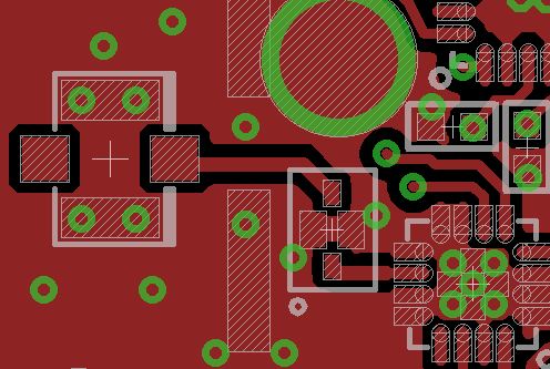
FYI, the reason I snake the PA control lines around the PA rather than going straight alongside YY_1 is that there isn't quite enough room for the routes between the pad vias and the resonators, and layout is so tight, I don't want to try moving any components. They are low frequency digital lines, so snaking around shouldn't cause any issues even if it isn't pretty.
Edit:
FYI, the reason I snake the PA control lines around the PA rather than going straight alongside YY_1 is that there isn't quite enough room for the routes between the pad vias and the resonators, and layout is so tight, I don't want to try moving any components. They are low frequency digital lines, so snaking around shouldn't cause any issues even if it isn't pretty.
Last edit: 04 Apr 2015 20:08 by PhracturedBlue.
- octagon
-
- Offline
Less
More
- Posts: 58
04 Apr 2015 20:21 - 04 Apr 2015 20:52 #30800
by octagon
Replied by octagon on topic Single-Board Universal Module
I think the Vdd plane looks fine. Local bypassing may be more important to create low impedance to ground. DC resistance of Vdd plane should be no problem at these "power" levels.
Your layout is fine, the two DC output coils may couple but 90° will reduce this. Some coils are shielded, like the 0603 I suggested.
Increased space between coils helps of course too. It looks like there is room. I would not want to see dc/dc sidebands in the 2.4GHz output. A test program with no frequency hopping or spreading (direct carrier only) would easier show if the four RF sources pass sidebands from DC supply.
I would remove the restrict (layer 41, 42) on ground pour for the bypass caps around the micro-controller, I'd keep these inductance’s as low as possible even if not at problem at 40MHz.
Last edit: 04 Apr 2015 20:52 by octagon.
- Fernandez
-
- Offline
Less
More
- Posts: 983
04 Apr 2015 20:55 #30801
by Fernandez
Replied by Fernandez on topic Single-Board Universal Module
Oh I suggest also put a 47p DC block capacitor inline rf output. This could fit under the shield befor ipx. The shield just need small cutout.
- octagon
-
- Offline
Less
More
- Posts: 58
04 Apr 2015 21:44 #30802
by octagon
Replied by octagon on topic Single-Board Universal Module
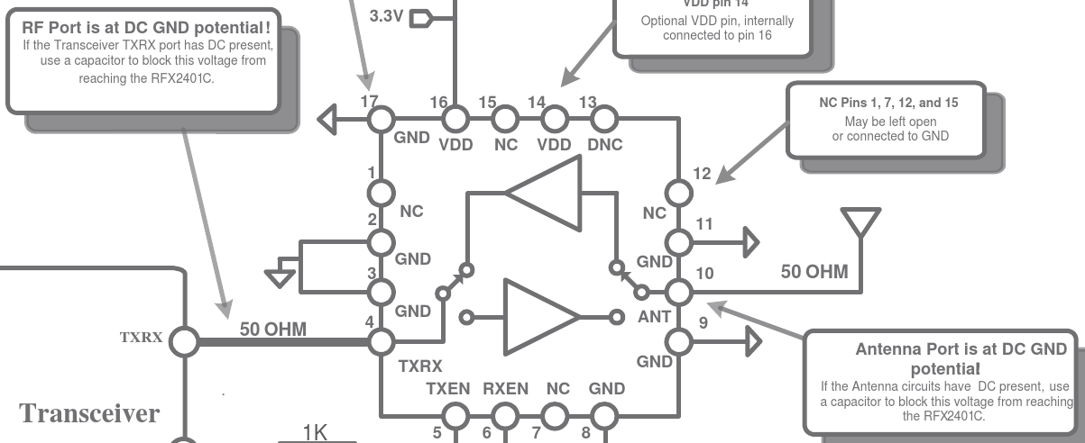
DC blocking for the RFX2401 should not be needed, in or out, unless you put DC on these lines that may pop the internal silicon capacitor.
Try using "teardrops" ULP on the board, less chance for bad etches on small lines.
Try using "teardrops" ULP on the board, less chance for bad etches on small lines.
- octagon
-
- Offline
Less
More
- Posts: 58
05 Apr 2015 20:25 - 05 Apr 2015 22:38 #30810
by octagon
Replied by octagon on topic Single-Board Universal Module
Inductor for DC/DC output can also be a shielded type (2.2uH min.) to reduce coupling between the two output coils. Like:
You could get a couple each to see if the conducted noise is less with the shielded types.
- 445-172392-6-ND
- SRP2010-2R2MDKR-ND
- 535-12278-6-ND
You could get a couple each to see if the conducted noise is less with the shielded types.
Last edit: 05 Apr 2015 22:38 by octagon.
- PhracturedBlue
-
- Offline
Less
More
- Posts: 4403
06 Apr 2015 02:19 #30820
by PhracturedBlue
Replied by PhracturedBlue on topic Single-Board Universal Module
Well, on my 3rd board, the nrf chip doesn't output any RF signal. I'm at a loss, since the solder joints all look fine, and it responds to SPI traffic. It also toggles the PAEN pin as if it is transmitting, but there is no rf output. Even if I probe right at the chip pin.
Possibilities:
1) the solder joints aren't ok somewhere, and I just can't see it
2) the NRF chip is bad
3) I installed the wrong component somewhere and am loading down the RF pin(s)
4) ???
Possibilities:
1) the solder joints aren't ok somewhere, and I just can't see it
2) the NRF chip is bad
3) I installed the wrong component somewhere and am loading down the RF pin(s)
4) ???
- hexfet
-
- Offline
Less
More
- Posts: 1971
06 Apr 2015 03:28 #30822
by hexfet
Replied by hexfet on topic Single-Board Universal Module
Oscillator not starting?
- octagon
-
- Offline
Less
More
- Posts: 58
06 Apr 2015 04:01 - 06 Apr 2015 04:03 #30823
by octagon
Replied by octagon on topic Single-Board Universal Module
Can you pick up 16MHz with the o'scope?
Do you have DC voltage on pins 12, 13?
You may be able to pick the LO with a inductive probe, like 5 turns of thin magnet- or wire-wrap wire, soldered to the end of a thin flexible coax, connected to spectrum analyzer. A 3mm coil held over the center of the chip may pick it up, it does on the Cypress chip (800MHz below output).
Last edit: 06 Apr 2015 04:03 by octagon.
- PhracturedBlue
-
- Offline
Less
More
- Posts: 4403
06 Apr 2015 04:45 #30825
by PhracturedBlue
Replied by PhracturedBlue on topic Single-Board Universal Module
The oscillator is fine (which it would need to be for the PA_EN to flip). I don't have equipment to pick up a high-frequency signal (my rf explorer can only pick up 2.4-2.5GHz range, and I haven't been able to find a trace of that on the board with nrf enabled so far). Pins 12/13 are at 1.88V (just as they are on the working module). In fact all the pins seem to have similar DC voltage characteristics to the working module.
- vlad_vy
-
- Offline
Less
More
- Posts: 3333
06 Apr 2015 07:36 - 06 Apr 2015 07:37 #30833
by vlad_vy
Replied by vlad_vy on topic Single-Board Universal Module
Can it be bad inductance (shorted) on the path from VDD_PA (11) pin to ANT1 and ANT2 pins?
Last edit: 06 Apr 2015 07:37 by vlad_vy.
- moss
-
- Offline
Less
More
- Posts: 40
06 Apr 2015 12:40 - 06 Apr 2015 12:45 #30836
by moss
Replied by moss on topic Single-Board Universal Module
There is an expansion board for the RF-Explorer 15-2700MHz.
www.seeedstudio.com/depot/RFEM-WSUB3G-Module-p-1264.html
www.amazon.com/RF-Explorer-RFEM-WSUB3G-Module/dp/B00IF913O0
I'm getting one.
If the NRF chip is getting the power it needs and you cannot sniff any RF on the output pins,(some should remain even if "shorted") then maybe either the chip is toast, or it is not getting the code it needs.
Last edit: 06 Apr 2015 12:45 by moss.
Time to create page: 0.501 seconds
-
Home

-
Forum
-
Development
-
Development
- Single-Board Universal Module