- Posts: 28
Ultimate7e tutorial: Processor upgrade
- brummel
-
- Offline
STM32F103RET6 LQFP-64 STMicroelectronics 32-Bit 72 MHz Anzahl I/O 51
Just to make dubble sure about the Package and Pin numbers.
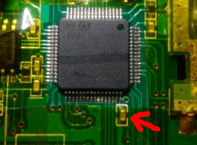
Another question, there is one capacitor right under the MCU , somebody knows it's value?
While a close inspection I saw fracture at one side of the cap (It wasn't me) but then it's a good occasion to fix it too.
Regards
Please Log in or Create an account to join the conversation.
- RobC62
-
- Offline
- Posts: 30
also on eBay: eBay item number:172431545473
Very inexpensive.
Not sure what the capacitor is as I don't have a 7E opened up at the moment.
Please Log in or Create an account to join the conversation.
- brummel
-
- Offline
- Posts: 28
It's the same
I have to desolder it for messureing and this wont survive the action. I told it has a little crack...
Please Log in or Create an account to join the conversation.
- silpstream
-
Topic Author
- Offline
- Posts: 244
Can you check if that capacitor is connected between pin 48 and gnd? If it is, then it is a decoupling capacitor and the STM datasheet calls for a 100nF capacitor there.
Please Log in or Create an account to join the conversation.
- brummel
-
- Offline
- Posts: 28
silpstream wrote: I didn't open up my tx.
Can you check if that capacitor is connected between pin 48 and gnd? If it is, then it is a decoupling capacitor and the STM datasheet calls for a 100nF capacitor there.
I say" yes" with my little electronic knowledge.
I looked in the datasheet too and found it named as Vdd2 ....I am right?
Used your picture:
Please Log in or Create an account to join the conversation.
- brummel
-
- Offline
- Posts: 28
I desoldered the processor with my cheap 30$ hot air station and soldered it with my iron.
Please Log in or Create an account to join the conversation.
- compman2
-
- Offline
- Posts: 65
I am looking for ideas? I ordered the processors from china what are the chances that the processors have a defect that keeps the usb from working? Is it possible that a component on the board is causing the problem, if so where might I look? I noticed on the mcu pin map in the wiki that there is a usb enable pin that needs to be drawn low, is there a way to manually do this to see if the usb will work?
I may reinstall the origional chip and see if the usb functions but I hate to keep swapping processors. I have also thought of purchasing a chip from digikey or mouser to ensure that I have a first quality processor.
I have checked and rechecked both processors for shorted pins by both visual inspection under magnification and with a multimeter with fine tip probes.
I would appreciate any help you can give.
computer nerd, hobby collector, proud father
Please Log in or Create an account to join the conversation.
- brummel
-
- Offline
- Posts: 28
Bought mine from Farnell for 10$ each. I've got them within 3 day's.
Please Log in or Create an account to join the conversation.
- silpstream
-
Topic Author
- Offline
- Posts: 244
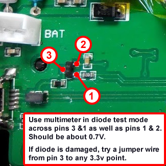
That part of the circuit basically enables a pull-up to 3.3v (through the 1.5K resistor) on the D+ pin when the USB enable pin is low. If the transistor is fried, replace it (SS8550) or run small jumper wire from 3.3v to the 1.5K resistor (side away from the D+ pin obviously).
I'll post a pic when I can.
Please Log in or Create an account to join the conversation.
- compman2
-
- Offline
- Posts: 65
computer nerd, hobby collector, proud father
Please Log in or Create an account to join the conversation.
- Sko
-
- Offline
- Posts: 2
Please Log in or Create an account to join the conversation.
- silpstream
-
Topic Author
- Offline
- Posts: 244
Have you guys tried uninstalling and reinstalling your windows drivers btw? Also check in windows device manager to see if it shows up at all.
One last thing (a bit silly but I thought I'd mention since it happened to me), you DID remove the jumper across the boot0 pin after flashing right?
Please Log in or Create an account to join the conversation.
- compman2
-
- Offline
- Posts: 65
I had tried uninstalling and reinstalling windows usb drivers eariler with no luck. I think they are working right as my other U7e connects correctly.
Tested the transistor and it seems to be good. Negative lead on multimeter to pin 1 and positive on pin 3 or pin 2 give me an identical reading. Reverse the negative and positive and get no reading. Also all other pin combinations give no reading either with either polarity. From what I have read on the internet this should mean the transistor is good.
Is there any harm in putting the jumper on pin 3 to 3.3v source if the transistor is good? Thought I might try this before trying another processor swap. Also is the positive voltage on the TMS,TCK,RST pin header an appropriate place to get the 3.3v?
If this fails I will order another processor from mouser or digikey for my next swap.
computer nerd, hobby collector, proud father
Please Log in or Create an account to join the conversation.
- silpstream
-
Topic Author
- Offline
- Posts: 244
I believe that the programming header is 3v3. Check with a multimeter to be sure.
No real harm done in adding the jumper, but to be honest, if the transistor is good (your description tells me it is), you shouldn't actually need to do this. You can probe pin 3 with a multimeter to see that you get 3v3 there when the power is turned on and you are in programming mode. If you do, then adding the wire does very little.
Also FYI (since I read back a couple of posts and saw this question posed), the correct thing for the transmitter to do after having the bootloader flashed is to go into programming mode even if the EXT button is not pressed, as it has no firmware to boot into. After firmware is flashed, it should then boot into USB mode if the onboard flash has never been formatted to FAT before, even if the ENT button is not pressed.
Please Log in or Create an account to join the conversation.
- compman2
-
- Offline
- Posts: 65
I will check the pin 3 when in programming mode to see if there is voltage there. I am assuming that I put the ground to the board ground and positive probe to pin 3 carefully. When I pulled the MCU it didn't look like the pin 3 pad had a trace going anywhere. In fact on my other U7e I pulled the pads for 2,3, and 4 and yet have a working device (which I love). I am assuming that when in programming mode the chip itself routes the voltage to pin 3.
computer nerd, hobby collector, proud father
Please Log in or Create an account to join the conversation.
- silpstream
-
Topic Author
- Offline
- Posts: 244
Please Log in or Create an account to join the conversation.
- offspringfan
-
- Offline
- Posts: 7
I just ordered two STM32F103RET6 for ~3,50€ each. I'm planning to use a cc2500 module and FrSky x4rsb receiver.
Is there any chance of getting advanced telemetry to work?
Please Log in or Create an account to join the conversation.
- Whatsinaname
-
- Offline
- Posts: 40
I have two devo7e's and I would like to upgrade the processor on both (one and then the other).
I found where to get the processors but I wanted to verify if this programmer can be used.
ST-Link STM8/STM32 v2 Programmer and Emulator
Many thanks.
Please Log in or Create an account to join the conversation.
- RobC62
-
- Offline
- Posts: 30
eBay item number:252708033038
Please Log in or Create an account to join the conversation.
- Whatsinaname
-
- Offline
- Posts: 40
The item number you posted doesn't return any results.
Either way, I have gotten used to paying a bit more for items as long as they ship to Hawaii.
Ebay is almost always a crapshoot to get items shipped to Hawaii so I usually just get direct from suppliers.
Many thanks again and I already ordered the programmer and the processors in one go.
Please Log in or Create an account to join the conversation.


