- Posts: 58
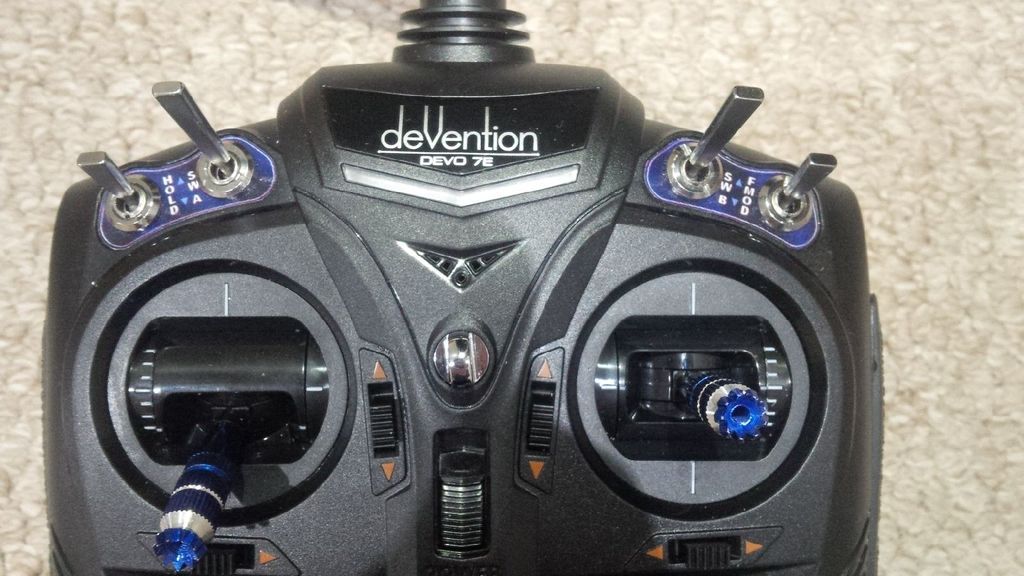
7e/Ultimate7e, adding the devo version 4in1
- kaligola
-
- Offline
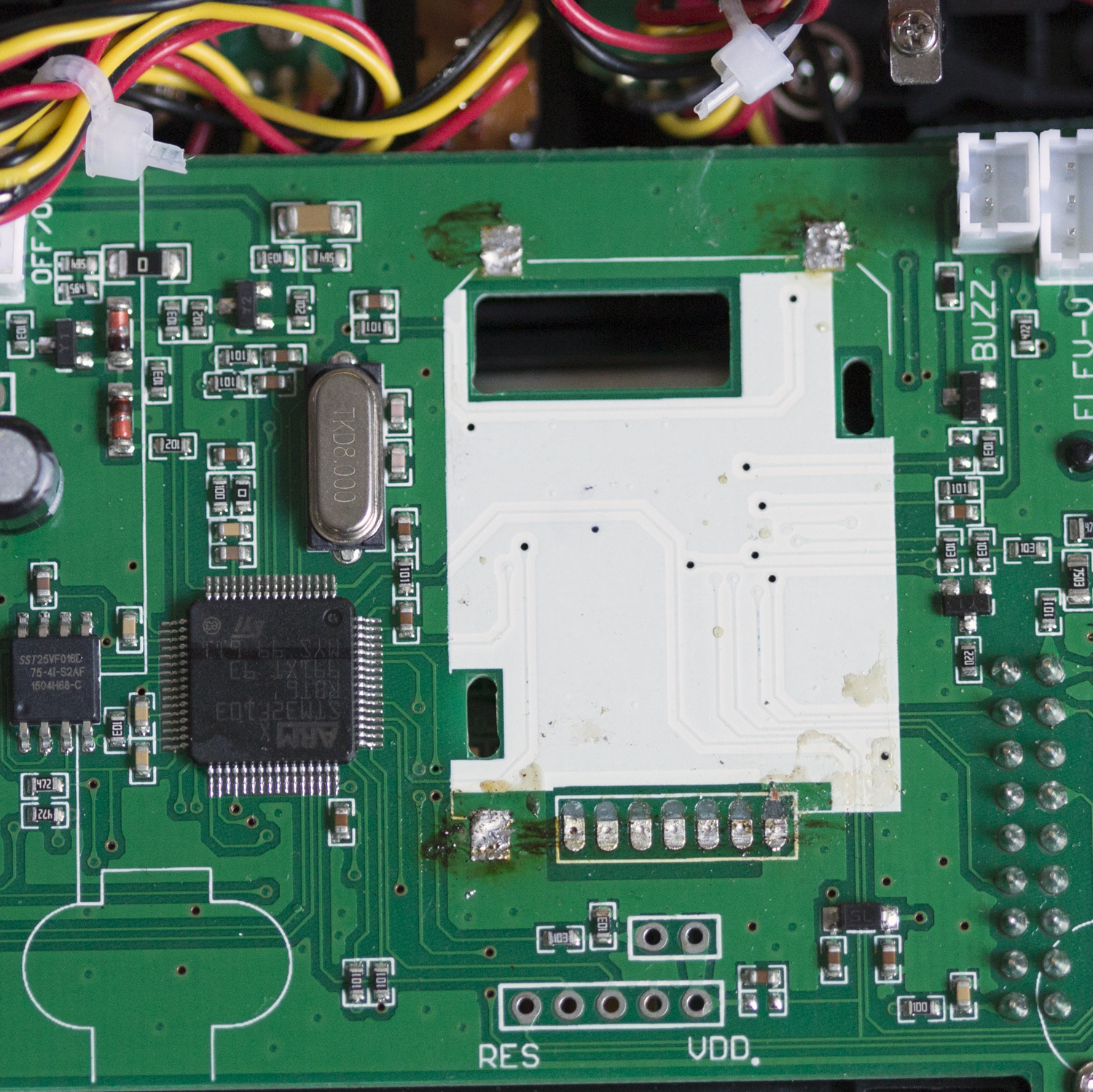
first get well unsoldered side of pads remove solder and get enough hot to move up before that part , the rest will came out even if glued because of temperature maybe helping with a cutter
anyway i see bit of solder point and the half gone is the part under the module. hope will be lucky, does not remain anything else than wait for module from walkera online
Please Log in or Create an account to join the conversation.
- victzh
-
- Offline
- Posts: 1386
In my experience the module is not glued to the main board, it's just fluxed so well that flux being sticky holds the module.
Please Log in or Create an account to join the conversation.
- dabiz
-
- Offline
- Posts: 6
Please Log in or Create an account to join the conversation.
- Phoenixx
-
- Offline
- Posts: 25
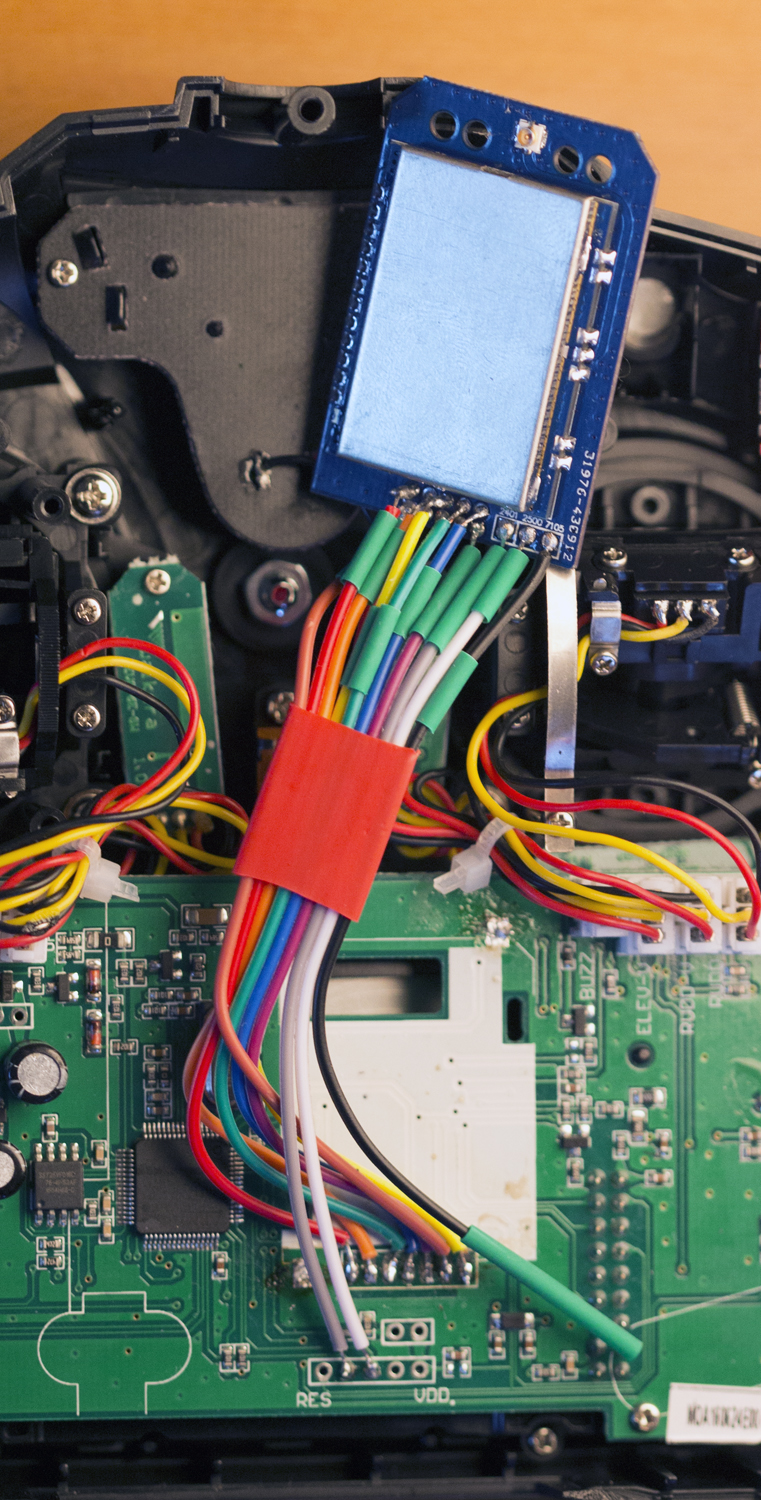
Thanks to HappyHarry for the photo's, it made it easy to follow.
Please Log in or Create an account to join the conversation.
- dabiz
-
- Offline
- Posts: 6
Please Log in or Create an account to join the conversation.
- HappyHarry
-
Topic Author
- Offline
- Posts: 1136
Phoenixx i'm glad they were of some help
Please Log in or Create an account to join the conversation.
- Phoenixx
-
- Offline
- Posts: 25
Please Log in or Create an account to join the conversation.
- HappyHarry
-
Topic Author
- Offline
- Posts: 1136
Please Log in or Create an account to join the conversation.
- CesiumSalami
-
- Offline
- Posts: 51
I did want to post the Hardware.ini configuration for people though. This is a http://www.banggood.com/CC2500-NRF24L01-A7105-CYRF6936-4-In-1-RF-Module-For-Walkera-D7E-D10-Transmitter-p-1096707.html4-in-1 unit purchased from Banggood .
Thanks so much for putting together the graphics to make this install a lot easier. Sheeeeesh - I dunno - I didn't even do the MCU part and I thought the diode mod (useless now) was a walk in the park compared to this
; enable-cyrf6936 = B12
  has_pa-cyrf6936 = 1
; enable-a7105    = A13
; has_pa-a7105    = 1
 enable-cc2500   = A14
 has_pa-cc2500   = 1
 enable-nrf24l01 = A13
 has_pa-nrf24l01 = 1
; enable-multimod = A13
ALMOST A FAIL
Please Log in or Create an account to join the conversation.
- TheSFReader
-
- Offline
- Posts: 64
However, I noticed that the trace/signal arrived via a Via/through-hole and that some solder adhered to that hole, so decided to "just try".
As it happens, all wires soldered nicely, and the contact seems good enough for the different modules to be recognized. Will have to test more thoroughly in "live" conditions.
For now, I've no use for the 2500, so like CesiumSalami, left the MPU alone. Will revisit if necessary.
Please Log in or Create an account to join the conversation.
- dabiz
-
- Offline
- Posts: 6
I haven't done any research on the 4in1 module or code yet. Can I update the firmware on the banggood devo 4in1 module? If so, any reason I can't change it to accept combos of 2 select pins to activate the 4 different modules instead of using my demuxing IC? I'm assuming there's an MCU on that module to activate the various rf chips...
Thanks for the help! Very awesome work done on the devo and deviation.
Please Log in or Create an account to join the conversation.
- victzh
-
- Offline
- Posts: 1386
You can't reprogram MCU on the Banggood module - the author of this module is quite secretive and we don't know what is this. You definitely can try.
Please Log in or Create an account to join the conversation.
- SuperFLY
-
- Offline
- Posts: 10
Unfortunately I did not have enough colors to dedicate each connection to a unique color so I had to double up. Looking at my photo I have used the white and green wires twice. The white and green that are all the way to the right on the module go to the pin header on the pdb not the pads where the original module was removed. Is this looking correct?
Please Log in or Create an account to join the conversation.
- CesiumSalami
-
- Offline
- Posts: 51
Things look good EXCEPT i can't see where your Red (VIN) attached to the 6th contact goes... Does that attach on the backside below the yellow wire?
Also ... sheesh - how did you remove the original module so cleanly ? looks great.
Please Log in or Create an account to join the conversation.
- SuperFLY
-
- Offline
- Posts: 10
I removed the stock module by using solder wick on the three main points and as much as i could on the pads for the connections. Then carefully lifting the module from the top making a hinge from the traces. When it was at about a right angle i ran a blade and cut the traces in half. Risky but i think im ok....
Thanks!
Please Log in or Create an account to join the conversation.
- SuperFLY
-
- Offline
- Posts: 10
Please Log in or Create an account to join the conversation.
- CesiumSalami
-
- Offline
- Posts: 51
regarding the removal method: LOL that's exactly what I did. Looks like you just did a cleaner job #skillz
purple LED: the answer to this is out of my league, sorry. Good luck!
Please Log in or Create an account to join the conversation.
- victzh
-
- Offline
- Posts: 1386
Please Log in or Create an account to join the conversation.
- SuperFLY
-
- Offline
- Posts: 10
Please Log in or Create an account to join the conversation.
- CesiumSalami
-
- Offline
- Posts: 51
Could someone confirm that the product below would be a suitable dummy load for this application?
(I do have an SMA connector on mine)
www.banggood.com/SMA-Male-RF-Coaxial-Ter...50-Ohm-p-927353.html
I just don't know enough about this to say for sure.
Please Log in or Create an account to join the conversation.


