- Posts: 62
7e/Ultimate7e, adding the devo version 4in1
- Texacate
-
- Offline
But can anyone enlighten me whether or not one should tie off the unused select line on the 4in1? And if we should, to which power rail? GND, batt+, 6v, 5v 4.3v, 3.3v ?
Because the if module has pull-ups or pull-downs on those pins, AND they pull to the inactive/disabled state (which would make sense) then leaving it floating would be okay. What little documentation we have on the Banggood site doesn't say.
Cheers and Thanks
Please Log in or Create an account to join the conversation.
- Texacate
-
- Offline
- Posts: 62
HappyHarry wrote: I didn't say to change the diode bud, I said you need to work out why you only get 3.*v at the module header while getting 5+v at the diode. there is something wrong with your 7e that is causing this.
as there is only 1 diode between the battery voltage and the module header it means that if you are getting 5v at the diode the minimum you should see at the header is 4.3v (5v - 0.7v maximum for the drop across the diode) plus the 4in1 needs >3.6v to work properly so when you said you have only 3v at the header it has me worried
If I understand the +5v side, of the diode, of which you speak, one can also power the 4in1 using the the right hole for the (nonexistent) 2 pin jumper, in upper-left section of the PCB (near the header for the 7E's power switch). They are the same trace. Avoids soldering to that surface mount diode.
Please Log in or Create an account to join the conversation.
- Chimera
-
- Offline
- Posts: 51
Please Log in or Create an account to join the conversation.
- CesiumSalami
-
- Offline
- Posts: 51
Still going strong 5 or so months later.
Please Log in or Create an account to join the conversation.
- Texacate
-
- Offline
- Posts: 62
Please Log in or Create an account to join the conversation.
- HappyHarry
-
Topic Author
- Offline
- Posts: 1136
yeah iirc that point is an option for vbat also, but that and the soldering to the diode are only needed if you lift the +ve pad on the rf board header as that pad provides ample voltage for the 4in1
Please Log in or Create an account to join the conversation.
- Whatsinaname
-
- Offline
- Posts: 40
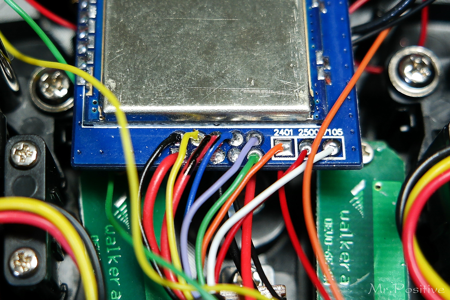
I followed the instructions precisely and only wired 3 modules (cy, nr and a7105).
I am able to fly my dsm2/dsmx and afhdsa/afhds2a quads.
I was having range issues with dsm2/dsmx but once I reverted from the Apr2017 nightly to the v5 stable I am good to go.
Please Log in or Create an account to join the conversation.
- jayodas
-
- Offline
- Posts: 13
Please Log in or Create an account to join the conversation.
- RobC62
-
- Offline
- Posts: 30
Please Log in or Create an account to join the conversation.
- jayodas
-
- Offline
- Posts: 13
Please Log in or Create an account to join the conversation.
- RobC62
-
- Offline
- Posts: 30
I must admit the first time I modded a 7E with a module I swiped from an old Skyrc NASA tx, that bit caught me out as well. Took two days to get the answer! Lol!
Please Log in or Create an account to join the conversation.
- logix200
-
- Offline
- Posts: 10
Thank you for your post.
I added two 3-position switches to my radio then according to your instructions I replaced a stock module with a 4in1 module. As a result the 4in1 module and two 3-position switches work normally.
By the way a HOLD switch didn't work after modifying.
Note: while I was removing the stock module from the radio, I damaged half of #4(purple wire) and #5(green wire) pads.
So I disconnected the 3-position switches from the radio, but likewise the HOLD switch didn't work.
My radio's MCU wasn't upgraded.
Do you know the factors that can interfere with the signal of the HOLD switch in the process of adding the 4in1 multi module?
My native language isn't English and my knowledge of electric and electronics is novice level.
HH, I really need your help.
Please check the photos below.
Thanks in advance.
Please Log in or Create an account to join the conversation.
- Texacate
-
- Offline
- Posts: 62
Please Log in or Create an account to join the conversation.
- compman2
-
- Offline
- Posts: 65
computer nerd, hobby collector, proud father
Please Log in or Create an account to join the conversation.
- darthnugget
-
- Offline
- Posts: 29
Please Log in or Create an account to join the conversation.
- kabo
-
- Offline
- Posts: 32
Please Log in or Create an account to join the conversation.
- darthnugget
-
- Offline
- Posts: 29
I know I can't be the only one to do this, I have seen a couple photos on this forum where someone replaced it with a larger sized diode. Not sure what it's purpose is on this thing but without it the TX functions but it can't find the CRYF module.
Please Log in or Create an account to join the conversation.
- Maxner
-
- Offline
- Posts: 32
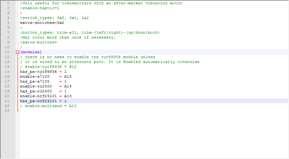
I would like to use all 4 protocols. Can someone please the appropriate hardware.ini post - there are already different versions in the forum, so I am unsure ...
Many Thanks
Please Log in or Create an account to join the conversation.
- Texacate
-
- Offline
- Posts: 62
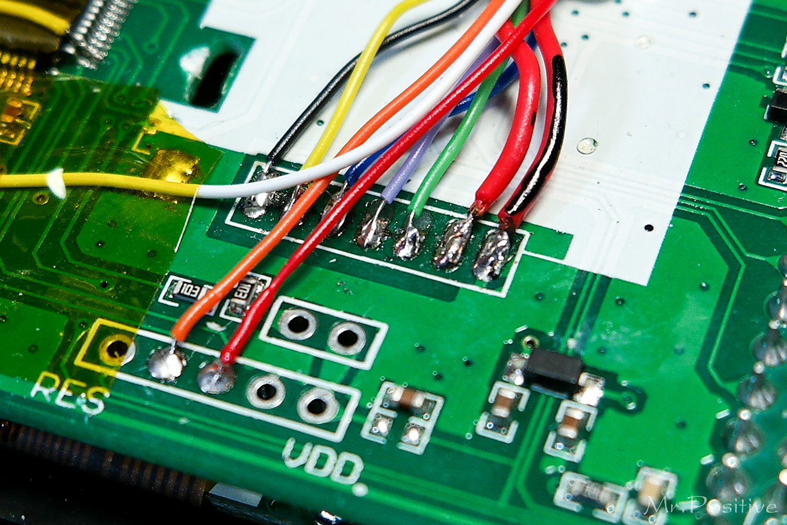
On 7E main board:
A13 == 2nd thru-hole (RES [o o o o o] VDD), labeled TMS in some photos
A14 == 3rd thru-hole (RES [o o o o o] VDD), labeled TCK in some photos
A15 == LQFP64 pin #50 == PA15 of the STM32F103RBT6 MCU
Therefor, if you connected the pin labeled 2401 on the 4in1 to the 2nd thru hole on the 7E main board, then you represent that in the hardware.ini with the lines:
enable-nrf24l01 = A13
has_pa-nrf24l01 = 1
Please Log in or Create an account to join the conversation.
- nin0ngfpv
-
- Offline
- Posts: 2
Please Log in or Create an account to join the conversation.


